
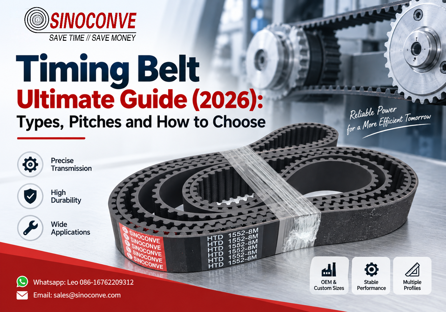
Timing Belt Ultimate Guide (2026): Types, Pitches and How to Choose
A timing belt transmits torque with teeth, not with friction. That one design choice explains most of what follows — why the ratio holds at 2:1 no matter how the load swings, why a 20 mm wide belt can index a print head to within ±0.1 mm for a whole shift, and why "just tighten it more" never repairs a synchronous drive. It cannot slip. If the driven pulley moves while the driver does not, something has already broken or stripped.
We meet both worlds on the same service trip. Out at the pit, the belts that matter are 1,200 mm wide and move 400 t/h of blasted rock; those are the ones documented on our rubber conveyor belt page. Inside the workshop 300 m away, the belt that stops the plant is often 9 mm wide and drives a servo axis on a pouch filler. Different products, same discipline: match the belt to the load, or pay for the mismatch every month.
SINOCONVE is a conveyor belt manufacturer based in Ningbo, China. EP and NN fabric-core belts, steel cord belts, plus heat-resistant, oil-resistant, flame-resistant and chevron covers are the core of our business. We also mold and grind PU and rubber synchronous belts for OEM accounts, open-ended and endless, from 2 mm pitch through 20 mm pitch. The questions collected here are the ones buyers email us every week.

01What a Timing Belt Actually Does
A synchronous belt is a cord layer that carries the load, wrapped in a compound that has been molded into teeth. The cord does the pulling. The teeth only keep belt and pulley in step. Engineers who forget that division of labour blame the teeth for failures that started in the cord, and they order the same belt again with a thicker back.
Why engagement beats friction here
A friction drive needs preload, and preload is always a compromise: tension enough for peak torque and you overload the bearings, run it slack and it slips on the shock. Tooth engagement removes the trade-off. Transmitted torque then depends on tooth shear area and cord tensile, not on how hard the belt was tensioned. A 20 mm wide HTD 8M drive on a conveyor indexer in one of our packaging accounts ran for years with only 2–3 mm of measured mid-span deflection and never lost position, even with a 35 N·m jam load hitting the driven shaft.
The distinction between friction drives and tooth drives is treated in full elsewhere: see our comparison of V-belt vs timing belt, and the profile data behind it in our V-belt ultimate guide. Short version, and this is the only place we will say it here: if the driven shaft must hold position, or the ratio must stay exact, specify teeth.
A worked example of the gain
Take an 8M profile (8 mm pitch), 32-tooth driver at 1,450 rpm, 64-tooth driven pulley. Pitch diameter of the small pulley is 32 × 8 ÷ π ≈ 81.5 mm, so belt surface speed is roughly 6.2 m/s. The ratio is exactly 2:1. If pulley run-out stays under 0.05 mm and the belt is aligned to within 1 mm over the span, position repeatability at the load is comfortably inside 0.1 mm. That combination is why filling and labelling OEMs pay a premium for tooth drives on the main axis and keep a friction drive only for the outfeed rollers.
What teeth do not fix
Engagement will not correct misalignment, worn bearings, or a shaft that flexes under load. It also does not tolerate very small pulleys at high speed: bending a cord around fewer teeth raises bending stress sharply, and that is the mechanism behind most of the "the belt just snapped at 11 months" reports we hear. Fix the geometry first. Then choose the compound.
Field note from our engineers: At a bagging line in 42°C ambient, we cut open a 5M belt that had failed after nine weeks. The teeth were almost untouched. The glass cord had a single dry, whitish shear band 4 mm from the back edge — classic walking-off-the-flange damage, not a compound problem. A 1.5 mm shim under one bearing bracket and a re-alignment fixed it. Cost of the shim: less than a coffee. Cost of the nine-week failure cycle before that: three belts and one unscheduled weekend.
02The Tooth Profile Family at a Glance
Four families carry almost all industrial timing belt work. Between them they span a 25 mm pitch range and about four orders of magnitude in torque. Pick the family first; the pitch, width and length follow from it.
The four families
| Family | Pitches in use | Tooth shape | Typical band |
|---|---|---|---|
| Inch trapezoidal | 2.03–31.75 mm (0.080–1.250 in) | Straight-sided, rounded tip | Light conveyors, office machines, retrofit drives |
| Metric trapezoidal | 2.5–20 mm | Straight-sided, metric geometry | Machine tools, glass and textile lines |
| Curvilinear HTD | 3–20 mm | Round-tooth involute form | The industrial default for anything above 1 kW |
| High-torque curvilinear GT2 / GT3 | 2–8 mm | Modified curvilinear, deeper flank contact | Precision positioning, 3D printing, small robotics |
Table 1. The four timing belt profile families and the pitch ranges each one covers.
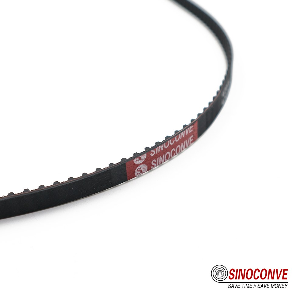
Tooth geometry decides everything downstream: how much torque a given width can carry, how small the driver pulley may be, and how much noise the drive makes at speed.
How we choose family in a first conversation
Two questions settle it. What is the continuous torque at the driven shaft, and what is the smallest pulley the machine layout allows? Everything in the four families below is molded in our own workshop, and the sizes we hold are listed on the timing belt product page. Below roughly 3 N·m, a metric T5 or a 5M is usually enough. From 10 to 60 N·m, 8M dominates because it matches common 30–50 mm shaft sizes and 20–50 mm belt widths. Above 200 N·m at low speed, the jump goes to 14M or 20M with a steel cord, and at that point you are buying a piece of capital equipment, not a consumable.
03Inch-Pitch Trapezoidal Profiles: MXL, XL, L, H, XH, XXH
This is the oldest family still in daily industrial use, and it survives because it is cheap, widely stocked and easy to buy in single pieces. The teeth are straight-sided with a rounded tip; the flank angle is shallow, so contact stress is higher than on a curvilinear tooth. For low-speed, low-power drives that is fine. For a 3 kW axis running 24/7 it is not.
Pitch values and capacity
| Profile | Pitch | Common widths | Typical torque band | Usual tooth counts |
|---|---|---|---|---|
| MXL | 2.032 mm (0.080 in) | 3.2, 4.8, 6.4 mm | 0.1–0.5 N·m | 14–72 |
| XL | 5.080 mm (0.200 in) | 6.4, 7.9, 9.5 mm | 0.5–2.5 N·m | 10–72 |
| L | 9.525 mm (0.375 in) | 12.7, 19.1, 25.4 mm | 2–12 N·m | 10–60 |
| H | 12.700 mm (0.500 in) | 19.1, 25.4, 38.1, 50.8 mm | 10–45 N·m | 14–48 |
| XH | 22.225 mm (0.875 in) | 50.8, 76.2, 101.6 mm | 45–150 N·m | 18–48 |
| XXH | 31.750 mm (1.250 in) | 76.2, 101.6, 127 mm | 120–450 N·m | 18–40 |
Table 2. Inch-pitch trapezoidal profiles. Torque bands are the ranges we commonly see quoted for one-inch-wide belt sections; always confirm against the specific cord and compound.
Where the inch profiles still win
MXL and XL remain the standard answer for instrument drives, small conveyors and anything being repaired to a drawing older than the engineer. A 9.5 mm wide XL belt driving a 25 mm roller at 300 rpm will run for years on 1.5 N·m. The trouble starts when someone replaces a worn L drive with an H "to be safe". The H pitches 12.7 mm, needs a 14-tooth minimum on the driver, and the existing 40 mm boss on the machine will not carry it. Now the bearing housing is being machined and the weekend is gone.
Two details that bite
First, capacity scales with width and pitch together, but not linearly. Doubling width roughly doubles tooth shear area and therefore torque capacity; doubling pitch more than doubles it because tooth depth grows faster than pitch. That is why going from L to H is not a 33% upgrade, it is closer to a 4× step in the same width.
Second, the trapezoidal flank has a clearance at the root. Debris such as fine sand or glass dust packs into that clearance at 5–10 g/h on an unsealed line and lifts the belt off the pulley within a shift. Curvilinear profiles handle the same grit rather better because the load line rolls instead of sliding.
04Metric Trapezoidal Profiles: T2.5, T5, T10, AT5, AT10
Metric trapezoidal belts are the pragmatic middle of the market. They are dimensioned in whole millimetres, they are stocked everywhere in Europe and Asia, and the AT variants shift the tooth deeper into the belt for a bit more shear area without changing the pitch.
T versus AT: the difference in one line
Same pitch, different tooth. AT profiles carry a longer, straighter flank and are designed for higher transmission loads in the same pitch. You cannot mix a T pulley with an AT belt and expect tooth life; they will mesh, badly, and strip within weeks.
| Profile | Pitch | Min. pulley teeth (typical) | Typical torque band | Common widths |
|---|---|---|---|---|
| T2.5 | 2.5 mm | 12 | 0.1–0.4 N·m | 4, 6, 10 mm |
| T5 | 5 mm | 10 | 0.5–5 N·m | 6, 10, 16, 25 mm |
| T10 | 10 mm | 12 | 5–40 N·m | 16, 25, 32, 50 mm |
| T20 | 20 mm | 14 | 40–160 N·m | 25, 32, 50, 75 mm |
| AT5 | 5 mm | 10 | 0.8–7 N·m | 10, 15, 20, 25 mm |
| AT10 | 10 mm | 12 | 8–55 N·m | 16, 25, 32, 50 mm |
| AT20 | 20 mm | 14 | 60–220 N·m | 32, 50, 75, 100 mm |
Table 3. Metric trapezoidal and AT profiles. Minimum pulley teeth are the values typically quoted for full load; lighter duty allows fewer.
Reading a T metric belt in the field
A T10 belt is easy to spot: 10 mm between tooth centres, and a 1,400 mm pitch length works out to 140 teeth. That arithmetic is the whole trick, and it is worth doing before you order. If your 1,400 mm is a measured outside circumference with a seam allowance, the belt will come up short by 10–30 mm once it is on the pulleys, because the pitch line sits below the back surface by roughly the tooth depth. Measure the pitch length, or send us the tooth count.
Why AT is showing up more often
Machine builders who used to fit T10 on a 25 mm width are moving to AT10 at 20 mm for the same duty. Less width, less inertia, less overhung load on the reducer output shaft. The trade is a pulley that costs slightly more and a belt that must come from a supplier who actually stocks AT geometry. For OEM lines that is a fair trade. For a repair truck in a distant province it is a stocking risk worth thinking about.
05Curvilinear HTD Profiles: 3M, 5M, 8M, 14M, 20M
HTD — high torque drive — was introduced to solve a specific problem the trapezoidal tooth could not: at pitch values above about 5 mm, the straight flank concentrates load on the tooth corner, and a loaded corner is where cracking begins. The curvilinear tooth spreads that load across the whole flank and lets the belt sit lower in the groove. In practice it means more torque per millimetre of width and a belt that tolerates a smaller driver pulley.
Pitch, capacity and practical size ranges
| Profile | Pitch | Common widths | Torque band, 1 to 2 tooth mesh | Where it usually lands |
|---|---|---|---|---|
| 3M | 3 mm | 6, 9, 15 mm | 0.3–2 N·m | Encoders, small indexers, medical pumps |
| 5M | 5 mm | 9, 15, 20, 25 mm | 1–9 N·m | VFFS jaws, labelling, sewing heads |
| 8M | 8 mm | 20, 30, 50, 85 mm | 10–65 N·m | The industrial workhorse: 1–15 kW drives |
| 14M | 14 mm | 40, 55, 85, 115, 170 mm | 60–280 N·m | Crushers, mixers, mill pinions, compressors |
| 20M | 20 mm | 115, 170, 230, 340 mm | 200–800 N·m | Slow, heavy, high-torque shafts |
Table 4. HTD profiles. Torque bands assume a typical glass or aramid cord and at least six teeth in mesh; below that, derate.
How to size within the HTD family
Start from the required torque at the driven shaft, not from the motor nameplate. Then add the service factor your line actually needs: a uniform load running eight hours a day wants 1.2; a jaw crusher or a press feed wants 1.8 to 2.2. Multiply, and you have the design torque. A 5 kW motor at 1,450 rpm delivers about 33 N·m; on a shock-loaded saw feed with a 2.0 factor you are designing for 66 N·m, which is squarely 8M at 30 mm width or 14M at 40 mm width. The 14M pulley will be heavier and more expensive, but it will also tolerate a 24-tooth driver instead of the 8M's 36-tooth minimum at that load.
The five-millimetre rule of thumb
Every profile has a minimum pulley tooth count, and going below it is the single most reliable way to break a belt early. As a first pass, keep driver pulleys at or above 14 teeth for 8M, 22 for 5M, and 28 for 14M unless the application is genuinely low torque. These are not absolute limits. They are the point where the engineering effort of going smaller stops being worth the belt life you lose. If you want to check what is normally held in stock, our timing belt range lists profile, width and length together.
06High-Torque Curvilinear: GT2, GT3 and Precision Positioning
GT profiles are the next refinement: the tooth flank is modified so contact moves closer to the root, the belt sits lower, and backlash under load drops. GT2 made its name in the 3D printing and desktop CNC world at 2 mm pitch. In industrial machines you will see GT2 and GT3 at 3 mm and 5 mm pitch on scanners, dispensing heads, and small gantries where position error is measured in hundredths of a millimetre.
GT2 versus GT3, and why the number matters
The difference is flank geometry and the resulting stiffness. GT3 carries a slightly deeper, more optimised flank and is usually specified with a fibre-glass or aramid cord and a low-elongation PU face. Practically, GT3 at 5 mm pitch and 15 mm width will hold a repeating position better than a standard 5M belt of the same width under reversing loads, because the tooth deflects less before it seats. How much better depends on the drive; a useful planning figure is 30–50% less tooth deflection than a comparable trapezoidal profile at the same load.
Where GT belongs and where it does not
Use GT when the job is positioning, when the axis reverses frequently, and when the load is modest. A 5 mm pitch GT belt at 15 mm width, 60-tooth driver, sees roughly 2–8 N·m of continuous torque — perfect for a pick-and-place head, wrong for a 7.5 kW conveyor drive, where you want 8M or 14M and a belt you can tension with a spanner rather than a torque wrench. Buying GT for a heavy drive costs three to five times as much per metre and buys nothing. Buying standard 5M for a 0.02 mm dispensing axis is cheaper per metre and costs you the position tolerance.
Other curvilinear geometries you will meet
Beyond HTD and GT there is a family of curvilinear metric profiles usually labelled with an S prefix, plus several proprietary round-tooth variants sold under their own names. All of them are geometrically close to HTD but not identical. Belt and pulley from different families will mesh and will run — for a while. The consistent failure signature is uneven wear on one or two teeth near the entry to the pulley, followed by a stripped tooth and a position fault. If you cannot confirm the pulley geometry, confirm it by measuring: pitch and tooth depth, with a caliper, on the pulley itself.
07How to Read a Timing Belt Part Number
Most ordering mistakes we handle start with a misread string. The good news is that the code is short and mostly logical once you know which block does what.
The four blocks
A typical designation has four pieces: profile, pitch, width, length. Written together, 5M-15-450 means 5M curvilinear profile at 5 mm pitch, 15 mm wide, 450 mm pitch length. That last number gives you the tooth count straight away: 450 ÷ 5 = 90 teeth. Not 90 teeth "approximately" — exactly 90, because a synchronous belt can only be closed at a whole number of pitches.
| Code | Profile and pitch | Width | Pitch length | Teeth |
|---|---|---|---|---|
| 5M-15-450 | 5M, 5 mm | 15 mm | 450 mm | 90 |
| 8M-30-1200 | 8M, 8 mm | 30 mm | 1,200 mm | 150 |
| T10-25-1400 | T10, 10 mm | 25 mm | 1,400 mm | 140 |
| AT10-32-2000 | AT10, 10 mm | 32 mm | 2,000 mm | 200 |
| 14M-85-3360 | 14M, 14 mm | 85 mm | 3,360 mm | 240 |
| XL-025-300 | XL, 5.08 mm | 6.4 mm (0.25 in) | 762 mm (30 in) | 150 |
Table 5. Decoding common belt designations. Inch-pitch belts usually carry length in inches and width in hundredths of an inch, which is where most transcription errors happen.
Pitch length is not the length you measure on the bench
Lay a used 8M belt flat on the floor and measure the outside surface and you will read about 4–6 mm more than the pitch length on a 1,200 mm belt, because the cord sits slightly inside the back. On very thick belts the gap is larger. If you send a supplier an outside length, expect to argue about the return freight. The safe procedure: count teeth, multiply by pitch, and order that number.
Double-sided and open-ended shorthand
Double-sided belts — teeth on both faces, used where one belt drives two counter-rotating shafts — usually carry a DA or DB prefix or suffix, where DA denotes teeth that are not symmetrical to the pitch line and DB a symmetrical construction. Open-ended belt is sold by the metre and joined, either by a mechanical fastener for low duty or by a vulcanised or welded joint when the joint has to run over the pulleys. In PU, a welded endless joint is common up to roughly 100 mm width; broader belts are usually specified endless from the start because the joint becomes the weakest link and the cost of a bad one is a line stop.
One more naming habit worth respecting: the tooth count on a synchronous pulley is written as the number of grooves, not the pitch diameter. Order "32-groove 8M" and you get what you asked for. Order "80 mm pulley" and you may get either 30 or 32 grooves, depending on which diameter the salesperson assumed.
08Cord Materials: Fiberglass, Aramid and Steel
The cord is the part of the belt you never see and the part that decides how long it lasts. Tooth wear you can inspect. Cord fatigue you cannot, until it fails.
Fiberglass: the default for most industrial belts
Glass cord is stiff, cheap, and dimensionally stable. Elongation at break is typically quoted in the 2.5–3.5% range, and at working load the belt stretches well under 1%, which is what keeps timing crisp in a normal drive. The weakness is bending fatigue. Glass filaments do not like to be flexed hard in one direction and then the other, so a glass-cord belt on a small driver pulley at high speed will fail in the cord long before the teeth wear out. One of our textile accounts replaced a glass-cord 5M belt every 11 weeks on a 15-tooth driver; moving to a 22-tooth driver at the same ratio took the same belt past two years.
Aramid: high modulus with impact tolerance
Aramid cord — you will see it written as aramid, and in Spanish-language search as aramida — is the choice when a drive has to survive shock. Cord tenacity is typically quoted around 2,700–3,000 MPa with elongation at break in the 3–4% band, and the fibre absorbs impact rather than snapping. That makes aramid belts a common fit on punched or stamped feed lines, on saw carriages, and on any axis where a jam happens weekly. The trade-off is cost, a slightly softer timing under reversing load, and more sensitivity to how it is finished: an aramid cord must be bonded properly to the compound, because the same toughness that resists impact also makes a weak interface fail fast.
Two of our own write-ups go deeper on this if the choice is live for you: aramid fibre versus steel cord in PU timing belts, and the strength case in aramid fibre PU timing belts.
Steel: maximum load, minimum tolerance for small pulleys
Steel cord gives the highest tensile of the three, with elongation at break usually below 2%, and it holds length better than anything else over years of service. It is the normal choice for 14M and 20M drives on crushers, mixers and mill pinions, where dimensions are generous and speed is low. Put steel cord against a 16-tooth pulley in a reversing duty and it will fail at the wire level within a few hundred thousand cycles. If the layout forces a small pulley, the cord has to change.
| Cord | Elongation at break (typical) | Length stability | Small-pulley fatigue | Relative cost |
|---|---|---|---|---|
| Fiberglass | 2.5–3.5% | Very good | Poor below 18 teeth | Low |
| Aramid | 3–4% | Good | Fair, best above 20 teeth | Medium to high |
| Steel | Under 2% | Best in class | Poor below 22 teeth | High |
| Polyester | 10–14% | Moderate | Good | Lowest |
Table 6. Cord comparison. Figures are the ranges typically quoted in cord and belt literature and will vary by construction; they are a screening tool, not a datasheet.
Field note from our engineers: A customer sent back a 14M belt that had lasted four months on a hammer mill. Teeth looked new. When we sectioned it, the steel cord showed fretting marks in one 300 mm zone only — the zone that ran over the small pulley. Driver had 19 teeth on a 20 mm pitch, which puts the bending stress far above what a steel cord wants. We quoted a 28-tooth driver and an idle to keep the centre distance, and the same belt pattern has now run well past a year. Nothing about the belt was wrong. The pulley was too small for the cord.
09Tooth-Face Compounds: HNBR, CR and PU
Below the cord sits the compound, and the compound has to survive abrasion, oil, heat and sometimes a wash-down with caustic every night. We build timing belts for customers in packaging, textile and automotive aftermarket channels, and the same question comes up every time: PU or rubber? The honest answer is that it depends on temperature and chemistry, and the price difference is smaller than the downtime difference.
You will also find our friction-drive side here if you need the other half of a drive package: as a transmission belt manufacturer and separately as a V-belt manufacturer, we quote wrapped and raw-edge V-belts to the same plants that buy our synchronous belts, which is useful when one drive on a line has to stay friction-driven.
PU: the default for synchronous belts
Polyurethane is cast or extruded around the cord and then cut into teeth, or molded in a closed tool. Shore A hardness on timing belt backs is normally 85–95, and the material survives continuous service from about −30°C up to +80°C, with brief excursions to +90°C acceptable if the load is light. Abrasion resistance is excellent and the material is naturally resistant to most oils, greases and cutting fluids. What it does not like is standing hot water above roughly 60°C, steam, and prolonged contact with strong alkalis, where hydrolysis softens the surface and the teeth start to round off. PU belts are also easy to make endless by welding, which is why they dominate open-ended OEM business.
CR: chloroprene for hot and dirty
Rubber timing belts usually use a chloroprene-based compound at Shore A 70–78. It tolerates continuous temperatures from around −20°C to +100°C and shrugs off ozone and weather. Its abrasion resistance is lower than PU, but when the ambient air is 85°C and there is clinker dust in it, PU will lose the race. We specify CR tooth faces for kiln-adjacent drives, dryers and engine-room auxiliaries where the belt is warm all day and nobody is going to change the environment.
HNBR: heat plus oil in one compound
Hydrogenated nitrile handles roughly −30°C to +150°C continuously and keeps a good grip on oil resistance, which is why the automotive aftermarket moved to it. It costs more than CR, bonds to aramid or glass cord reliably, and holds tooth shape at temperatures where a CR belt has already softened enough to lose position. On a machine with a hot gearbox next to the timing axis, HNBR is often the difference between an 8-week belt and a 12-month belt.
| Compound | Shore A | Continuous range | Oil and grease | Abrasion | Best fit |
|---|---|---|---|---|---|
| PU | 85–95 | −30 to +80°C | Very good | Excellent | Packaging, robotics, open-ended OEM belt |
| CR | 70–78 | −20 to +100°C | Fair | Good | Warm, dusty plant environment |
| HNBR | 70–80 | −30 to +150°C | Very good | Good | Automotive auxiliary, hot gearbox zones |
| Food-grade PU | 85–92 | −20 to +70°C | Very good | Excellent | Food and pharma lines, wash-down areas |
Table 7. Tooth-face compound comparison. Ranges are the bands we quote for standard compounds; special grades can extend them in one direction at the cost of another property.
The three specials worth asking for
If the belt runs where food is open, ask for a food-contact grade in white or blue so fragments are visible; metal-detectable versions exist for the same reason. If the drive sits near a VFD with long cable runs, a static-conductive belt is a genuine safety item, not an upsell — surface resistance is usually specified in the 104 to 107 ohm range for those grades, and belts are tested, not assumed. Third, back coatings: a green or amber fabric back, or a PU back layer, changes friction on the back-side idler and protects the back from abrasion, and on some vertical form-fill-seal machines the back side is doing as much work as the teeth.
How to tell what you have
Cut a small piece and bend it hard. PU goes white at the fold and springs back; CR greys slightly and feels softer. The reliable route is to read the marking on the back: good belts carry profile, pitch length and width, and often a compound code. Where the back is blank, we ask for a 100 mm sample and identify the compound and the cord in-house before quoting, because quoting the wrong compound is how a customer ends up with a repeat failure and a supplier who no longer answers the phone.
10Pulley Matching: Diameters, Tooth Count and Teeth in Mesh
A correct belt on a wrong pulley is a very expensive way to burn a weekend. Four numbers on the pulley decide how long the belt lives: pitch diameter, outside diameter, groove count, and the number of teeth actually engaged.
Pitch diameter versus outside diameter
The pitch diameter is where the cord runs, and it is what you use for ratio and speed calculations. The outside diameter is what you measure with a caliper over the tooth tips, and it is always smaller, by twice the pitch line differential of that profile. Confusing the two is a classic cause of a delivered pulley with the wrong groove count.
| Profile | Pitch line differential (typical) | Example grooves | Pitch diameter | Outside diameter |
|---|---|---|---|---|
| 3M | 0.381 mm | 24 | 22.92 mm | 22.16 mm |
| 5M | 0.572 mm | 20 | 31.83 mm | 30.69 mm |
| 8M | 0.762 mm | 24 | 61.12 mm | 59.59 mm |
| 14M | 1.372 mm | 40 | 178.25 mm | 175.51 mm |
| XL | 0.254 mm | 24 | 38.81 mm | 38.30 mm |
Table 8. Pitch diameter = grooves × pitch ÷ π. Outside diameter = pitch diameter − 2 × pitch line differential. Differentials shown are the values typically published for these profiles.
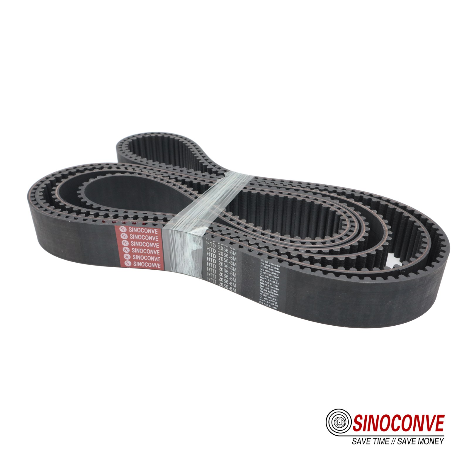
Count the teeth that carry load, not the teeth that are merely in the groove. Below six, tooth shear stress rises fast and the belt tells you about it.
Minimum teeth in mesh: the rule that prevents most broken teeth
The widely used floor is six teeth in mesh for trapezoidal and HTD profiles, and the more conservative practice is eight to ten where torque is heavy or the duty reverses. Teeth in mesh on the small pulley is worked out from arc of contact, not from belt wrap alone. For a two-pulley drive with a 2:1 ratio, wrap on the small pulley is about 180°, so a 24-tooth driver puts roughly 12 teeth in contact — comfortable. Push the ratio to 5:1 and wrap drops to about 120°, which on the same 24-tooth driver leaves about 8 teeth. Drop to a 14-tooth driver at 5:1 and you are near 4 teeth, and the belt will strip teeth at the root within weeks.
If the geometry will not allow more teeth in mesh, three fixes work in order of cost: grow the small pulley and reduce the ratio, add an inside idler to increase wrap, or move up a profile so each tooth carries less. Buying a wider belt does not fix a mesh problem. That is a mistake we will come back to in section 12.
Flanges, crowning and alignment
Flanges belong on at least one pulley, normally the driver, and on both if the centre distance exceeds about eight times the small pulley diameter or the drive is vertical. A crowning on a synchronous pulley is a bad idea — it changes the tooth form and creates edge loading. What a synchronous drive needs instead is parallel shafts and coplanar pulleys, within about 0.5° of angular misalignment and 0.25 mm of offset per 100 mm of centre distance. Belts that walk off are usually fighting misalignment, and a flange is only there to contain the walk, not to solve it.
Field note from our engineers: Two identical 8M drives on the same frame, same belt, same tension. One lasted 14 months, the other 5 weeks. The difference was 0.9 mm of pulley offset caused by a machined spacer that had been fitted backwards on one side. On the back-side idler you could see a bright polished stripe 3 mm wide. Nine tenths of a millimetre. That is how much alignment matters on a synchronous drive.
11Tensioning and Installation
A synchronous belt needs far less tension than people assume, and far more care in how it is fitted. Two-thirds of the "belt slipped" complaints we receive turn out to be either a loose belt that was never re-tensioned after run-in, or a belt that was levered over a flange with a pry bar and had its cord damaged in the process.
What initial tension is actually for
Teeth carry the torque, so tension is not there to prevent slip. It is there to keep the belt seated in the grooves on the slack side, to stop tooth ratcheting under shock, and to stop the belt floating out of mesh at speed. That is why synchronous drives run much slacker than a V-belt of the same width — and why over-tensioning is a real and expensive error: it loads the pulley bearings and reduces belt life by fatiguing the cord, with no benefit at all in transmitted torque.
The deflection rule, and how to apply it
The field rule is simple enough to use with a steel rule and a spring scale. Mid-span deflection should be about 1.5 mm for every 100 mm of span, applied with a force proportional to belt width and pitch. Some suppliers write the same rule as span divided by 64. For a 200 mm span that gives about 3 mm of deflection.
| Profile and width | Indicative deflection force at 200 mm span | Deflection to apply | Typical take-up travel to allow |
|---|---|---|---|
| 5M, 15 mm | 20–30 N | 3 mm | 1.5% of centre distance |
| 8M, 30 mm | 60–95 N | 3 mm | 2% of centre distance |
| T10, 32 mm | 70–110 N | 3 mm | 2% of centre distance |
| 14M, 85 mm | 180–280 N | 3 mm | 2.5% of centre distance |
Table 9. Starting tension guide for typical industrial drives. Confirm against the drive calculation for the specific installation; a belt that is too loose ratchets, one that is too tight shortens bearing life.
Sonic tension meters, and when they earn their cost
For drives above about 20 kW, or any drive where a stop costs more than a few thousand dollars an hour, a sonic tension meter pays for itself inside a year. You pluck the belt like a string, the meter reads frequency, and you convert frequency to static tension using belt mass per metre and span length. On a 30 mm wide 8M belt with a 200 mm free span, a correctly tensioned drive usually lands somewhere near 130–150 Hz. The advantage is repeatability: two maintenance shifts measuring the same drive get the same number, which is not true of a thumb pressed on a belt.
Fitting the belt without destroying the cord
Never roll a belt over a flange with a screwdriver, and never pry it on with a bar. Both practices put a local bend radius of a few millimetres on a cord that was designed for a 60 mm pulley, and the damage is invisible. Do it this way instead. Shorten the centre distance to the minimum on the slide, fit the belt by hand with the teeth engaged, then tension in even steps while turning the drive over by hand. Rotate at least two full revolutions and watch the belt tracking before you energise the motor. Then run the drive at no load for 30 minutes, stop it, and check tension again — a new belt settles and typically loses 15–25% of its initial tension in the first hours, mostly from cord seating rather than creep.
Run-in and re-tensioning schedule
Our standard advice for a new installation: check tension after 30 minutes of running, again after 8 hours, then at one week, then move to the plant's routine interval. After the first week the length is stable and further drift is minimal. Belts that need repeated tensioning every few weeks are telling you something else is wrong — a failing bearing, a soft mounting frame, or a pulley key that is creeping on the shaft.
12Nine Selection Errors We See in the Field
These are ordered roughly by how often we see them, not by how expensive they are. Some of them cost a belt. A few cost a production weekend.
Errors that come from the sizing sheet
Buying width to buy torque is the most common of all. A customer needs 40 N·m on a 5M drive, so he orders a 25 mm belt instead of a 15 mm. Width adds tooth shear area but nothing to cord bending stress, and the pulley flanges on his 20 mm pulley will cut the belt's edge within days. The correct move is usually to step to 8M at 20 mm, which lowers tooth stress and lets the driver stay a sensible size. The second sizing error is using motor nameplate power instead of real driven torque, which misses gearbox efficiency and the shock factor of the machine. The third is forgetting that a timing belt on a reversing axis sees the load twice per cycle, so a 1.2 service factor becomes 1.6 or higher.
Errors that come from the drawing
Ignoring teeth in mesh on the small pulley is the expensive one: it produces stripped teeth at the root, on the driver, usually within three months. Mixing tooth families is the quiet one — an HTD belt on a GT2 pulley looks correct and runs for weeks before the wear pattern appears. And plain arithmetic mistakes still happen more than anyone admits: a customer measures the old belt around the outside, orders that length, and the new belt is 8 mm short on a 1,400 mm drive. Count teeth and multiply. Every time.
Errors that come from the stores and the vendors
Buying on price alone without asking what cord is inside is a real risk, because the cheap belt is nearly always a glass cord in a soft compound, and it will fail in exactly the application where aramid or steel was needed. There is also a distribution question worth thinking about: a conveyor belt distributor who stocks 40 profiles locally will get you running on a Sunday, while a direct import at 20% lower unit price with a 45-day lead time will not. Both models are legitimate. Not knowing which one you bought is the problem. Finally, never accept unmarked belts where the profile is not readable on the back — you cannot verify a length or a compound on a blank belt, and any claim you make later is unprovable.
| Error | What you see in the field | What actually fixes it |
|---|---|---|
| 1. Adding width instead of pitch | Edge fraying, belt sits proud of the pulley | Step up a profile; keep width within the pulley face |
| 2. Fewer than six teeth in mesh | Driver teeth sheared flat at the root | Bigger small pulley, inside idler, or larger pitch |
| 3. Mixing tooth families | Uneven wear on two or three teeth, then a strip | Measure the pulley geometry, replace belt and pulley as a set |
| 4. Sizing on average torque | Tooth failure during a jam, not during normal running | Use peak jam torque with a 1.8–2.2 factor on shock duty |
| 5. Outside length ordered as pitch length | Belt will not fit, or will not tension | Count teeth and multiply by pitch |
| 6. Steel cord on a small pulley | Belt snaps with teeth still intact | Glass or aramid cord, or more pulley teeth |
| 7. Wrong compound for the environment | Rounded teeth, softened surface, oil swelling | Match PU, CR or HNBR to temperature and chemistry |
| 8. Prying the belt onto the pulley | Early cord failure at one point on the loop | Slide the centre distance in; fit by hand |
| 9. No take-up allowance in the frame | Belt runs loose after a week with no way to fix it | Machine in 2% centre-distance travel at the design stage |
Table 10. Nine errors, their visible symptoms, and the fix that actually works. If two or more of these describe your drive, fix the geometry before ordering another belt.
13Where Timing Belts Earn Their Place, Industry by Industry
Timing belts are unglamorous and they are everywhere: inside machines that fill your bottles, print your labels, wind your yarn, move your parcels and, in the aftermarket, under the bonnet of the car in the car park. Here is what we actually see in each sector, and the profile that keeps coming up as the sensible answer.
Packaging and form-fill-seal machines
This is where the volume is. A vertical form-fill-seal machine typically uses 5M or T5 belts to drive the film advance and the jaw carriage, with widths from 15 to 25 mm, and the belt is often expected to hold position within 0.5 mm through 60 cycles per minute. The drive survives on tooth accuracy and clean running: any debris on the belt face shows up as a film-length variation within an hour. If your line runs pouch filling, our notes on timing belts for vertical packaging machines and coated belts on packaging machines go into the belt construction choices in more detail. We also supply the matching food and packaging industry range on the plant side, from infeed to check-weigher.
Automation, robotics and pick-and-place
Small gantries and SCARA arms run 3M, 5M and GT profiles at 15 mm width, and the design driver is stiffness rather than torque: a 0.05 mm position error at the tool flange usually comes from belt stretch under reversing load, not from the servo. Belt manufacturers get asked for repeatability numbers and the honest answer is that repeatability is a property of the whole axis. What the belt contributes is low, predictable elongation — which is why aramid cord sells well here. Our automation OEM notes and the precision drive overview cover that trade in detail, and there is a separate piece on PU belts for packaging robotics.
Textile, nonwovens and printing
Textile machinery is a classic T5 and T10 market, and it is hard on belts for an unusual reason: high speed, many reversing axes, and a continuous lint load. Belts here run warm — we have measured 65°C on the back of a 20 mm T10 belt inside an enclosure — so compound choice matters almost as much as profile. Printing and converting machines lean the other way: 8M drives at 30–50 mm width, and an absolute requirement for zero drift over a shift, which mostly means a glass or aramid cord and a rigid frame.
3D printing, medical and laboratory equipment
GT2 and GT3 at 2–5 mm pitch, widths of 6 to 12 mm, low torque, and very high expectations about consistency. Buyers here often want a private-label marking on the back of the belt. We do that, and there is a page on private label timing belt supply if it is relevant to your programme. Medical pumps and analysers usually specify a food-contact or cleanroom-compatible compound, white, with no exposed fabric edge.
Automotive auxiliary and aftermarket
Automotive timing work sits in the aftermarket channel rather than the assembly line, and it is a different business: huge part-number breadth, small order quantities, and buyers who need a catalogue, not a consultation. Yet the technical questions are the same ones we started with here. Our automotive timing belt guide covers construction and buying practice, the aftermarket sourcing checklist is worth printing before a first order, and there is background on EPDM rubber timing belts for automotive use if you are comparing compounds.
Heavy industry, where the belt is a capital item
Mixers, crushers, hammer mills and kiln drives use 14M and 20M belts at 85–170 mm width and 60–800 N·m. Here the belt replaces a chain or a gearbox and the saving is in lubrication, noise and maintenance access. If your plant handles bulk material, you will want the pit-side side of our range as well — see the industrial conveyor belt we build for crusher lines and the mining and quarrying industry page, because a plant buying timing belts for a mixer is usually buying wide belts for the same site.
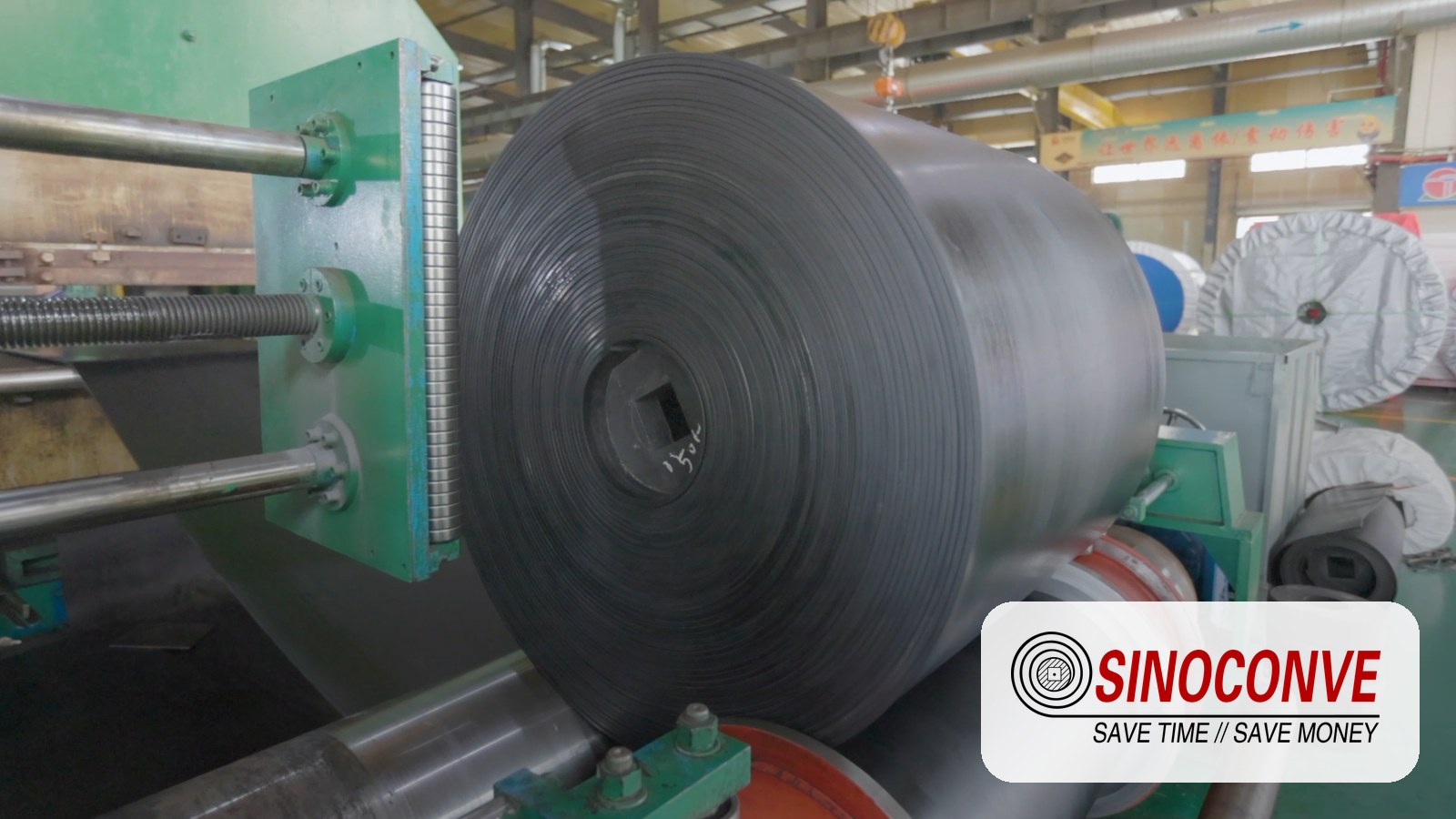
Sleeves are molded and then cut to width. Width tolerance and squareness of the cut decide whether a belt runs true or walks to one flange.
14Quality Checks and What to Ask a Supplier
Prices for the same nominal belt can differ by 40% between suppliers. Sometimes that is volume. Sometimes it is cord.
The six questions we would ask if we were buying
One: what cord is inside, and by what name do you call it? If the answer is "high quality fibre", ask again. Two: what compound is the tooth face, and what is the continuous temperature rating? Three: what is the measured pitch length tolerance, and is it checked on every batch or on a sample? Four: what is the width tolerance, and how is the cut edge finished? Five: for endless belts, how is the sleeve joined, and what is the joint strength relative to belt tensile? Six: what is the practical lead time for a repeat order, and how long will you hold the tooling if we developed a custom profile together?
What a credible answer sounds like
On pitch length, a well-run mold shop will hold a new belt within roughly 0.4 mm per metre of length and typically quote a tolerance band rather than a single number, because cord tension during molding varies slightly between sleeves. On widths, a cut tolerance of ±0.5 mm is normal above 20 mm width, and ±0.3 mm is achievable if the sleeve is ground after cutting. On joint strength for PU endless belts, a good welded joint is commonly quoted at 40–70% of belt tensile depending on width; anyone claiming 100% is selling you something the physics does not support.
Lead times, MOQ and validation
Industry norms, and yours may differ by profile: standard stocked profiles ship in 3–10 working days, non-standard lengths in 3–4 weeks, and custom tooling — a new mold for a specific tooth or a private-label back — takes longer, typically 4–8 weeks plus a sample round. MOQ for a standard profile is often one sleeve, which can be hundreds of metres; for custom work the tooling cost dominates and MOQ is negotiated. All of that is confirmed against the actual drawing and the actual duty, not against a price list.
Where to buy, and what the model costs you
Direct from a conveyor belt factory you get engineering support and tooling access, but you carry more inventory and longer lead time. Through a conveyor belt supplier with local stock you get a belt today, at a price that includes their holding cost. Many plants run both: stocked fast movers locally, and wholesale conveyor belts and volume timing belt programmes direct, with a small buffer on the shelf for the profiles that stop the line when they go missing. Our rubber timing belt wholesale guide walks through that split.
Put the belt side by side with the rest of the drive
One last habit that saves money: quote the timing belt and the friction belts on the same machine together. A line that uses a synchronous belt for its indexer often uses a heat resistant conveyor belt downstream and a PVC conveyor belt for light product handling, all from the same supplier. Small, single-source orders cost less to administer than three separate purchase chains, and one technical contact who knows the whole line beats three who each know a third of it.

15Timing Belt Questions We Get Every Week
What is the difference between a timing belt and a synchronous belt?
Nothing. They are the same product under two names, and both describe a belt with teeth that engage pulley grooves and hold an exact ratio. "Synchronous" is the more formal term and it is used in standards and datasheets; "timing" is what most maintenance teams say on the floor.
How do I work out the length of a timing belt I need?
Count the teeth on the old belt and multiply by the pitch. A 90-tooth 5M belt is 450 mm; a 150-tooth 8M belt is 1,200 mm. If the old belt is missing or unreadable, measure the outside circumference, subtract roughly twice the tooth depth, and then choose the nearest standard tooth count above that figure, because you can always take up slack with the slide but you cannot shorten a belt.
Can I replace a 5M belt with an 8M belt on the same pulleys?
No, and this is worth stating plainly because it gets attempted. Profile, pitch and groove form must match. You can move from 5M to 8M only by changing both pulleys as well, which also changes the centre distance because the pitch diameter of the same tooth count grows by 60%. Sometimes that is exactly the right upgrade. It is never a belt-for-belt swap.
Why are the teeth stripping off my belt?
Almost always because too few teeth are carrying load at the small pulley. Check the arc of contact: at ratios above 3:1 with a driver under 20 teeth, you can easily be down to four or five teeth engaged, and each of those teeth is then seeing several times its rated shear load. Look at the failure pattern too. Teeth sheared flat with a clean edge points to mesh or overload. Teeth rounded and polished points to abrasion or the wrong compound.
What is the difference between HTD and GT profiles?
Both are curvilinear, but GT has a modified flank that puts contact closer to the root, which reduces backlash under load and holds position better on reversing axes. HTD is the broader industrial standard with far more stock availability in 8M and 14M; GT is the precision choice, mostly seen at 2, 3 and 5 mm pitch. They are not interchangeable on a given pulley, even where the pitch matches.
Which is better for my machine, PU or rubber?
PU if the temperature stays under about 80°C and you want abrasion resistance and easy welding. Rubber — CR or HNBR — if the belt runs hot, from roughly 90°C into the 150°C band, or if there is oil and heat together. The exception is food and cleanroom work, where a food-grade PU usually wins on cleanability even in a warm room.
How much deflection should a timing belt have?
Apply about 1.5 mm of deflection for every 100 mm of free span, using a force matched to the belt width — 20–30 N on a 15 mm 5M, roughly 60–95 N on a 30 mm 8M. That is a starting point for new belts. Fresh belts settle, so check again after 30 minutes, after 8 hours and after a week.
Can I join an open-ended belt instead of buying endless?
Yes, and for low-duty or low-speed drives a mechanical fastener is a legitimate solution. It is rarely a good one on a high-speed or reversing axis, because the joint runs over the pulleys and it is the weakest point in the loop. For PU, a welded endless joint usually achieves 40–70% of belt tensile depending on width; if the drive depends on a joint holding at full load, order endless.
How many teeth should be in mesh?
Six is the widely used minimum, and eight to ten is the safer target for heavy or reversing duty. Work it out from the arc of contact rather than assuming, because a 3:1 ratio on a 20-tooth driver gives a very different number from a 1:1 on the same pulley.
What do you need from me to quote a timing belt?
Four things get a quote out the same day: profile and pitch, width, pitch length or tooth count, and the duty — torque or motor power with ratio, plus ambient temperature and whether the belt touches oil or food. Send a photo of the pulley face and the marking on the back of the old belt if anything is unclear. Most queries we cannot answer are missing exactly one of those items, and it is almost always the duty.
16Related Products You May Need
| Product | What it is | Typical duty |
|---|---|---|
| Timing belt | PU and rubber synchronous belts, MXL through 20M pitch | Positioning and index drives where the ratio must not drift |
| V-belt | Wrapped and raw-edge friction belts | Fans, pumps and simple ratio drives |
| EP rubber conveyor belt | Fabric-cored belt with EP carcass | Aggregate, sand and general bulk transport |
| Heat resistant conveyor belt | Covers rated for hot clinker and sinter | Cement, lime and foundry lines |
| PVC conveyor belt | Lightweight belt for unit handling | Parcels, food packing, warehousing |
| Full product catalogue | Every belt family we build, with grade options | Start here if you are specifying a whole line |
17Related Blog Posts
- PU timing belt vs rubber timing belt — compound choice, decided by temperature and chemistry rather than price.
- Aramid fibre vs steel cord in PU timing belts — the cord decision behind shock duty and small pulleys.
- Rubber timing belt applications
- PU timing belt surface precision
- V-belt vs timing belt: which one fits your line
- Rubber conveyor belt ultimate guide (2026)
- PVC conveyor belt ultimate guide (2026)
- Heat resistant conveyor belt ultimate guide (2026)
- Heat resistant belt failure modes and field fixes
- EP belt selection for stone crusher and aggregate plants