
Conveyor Roller Ultimate Guide (2026): Types, Materials and Load Ratings
A conveyor roller costs less than a metre of the belt it carries, and it is the component most likely to stop the plant. A 152.4 mm steel roller turning at 250 rpm that seizes will push its bearing housing past 130 °C inside an hour, scorch the cover above it, and walk the belt off line for 40 m in either direction. We have watched that happen on a 12 km overland conveyor and on a 6 m bagging line. The shell was sound in both cases. The seal had failed months earlier.
What follows is the reference we hand to buyers and maintenance planners before a roller enquiry arrives: the full type family, shell materials, bearing and seal construction, the arithmetic behind load ratings, and the installation habits that separate a 40,000-hour roller from a 4,000-hour one. If the theory is already settled and you only need the buying sequence, our shorter conveyor idler roller guide runs through it step by step. This page is the layer underneath that one.
SINOCONVE is a conveyor belt manufacturer in Ningbo, China, and rollers sit beside the belts in most of the systems we quote. EP and NN fabric-cored belts, steel cord belts, chevron and sidewall belts leave the same yard as 89 mm to 219 mm idlers with carbon steel, stainless or polymer shells. The two products fail together, so we prefer to quote them together.

01What a Conveyor Roller Does, and Why It Is Not a Pulley
Half of the confusion in roller enquiries comes from two words being used for one component and one word for two. A roller is a free-turning cylinder that supports the belt: no drive, no lagging, no torque to transmit. A pulley is the drum at the head or tail that drives or redirects the belt. Buyers who order "head rollers" are nearly always asking for a pulley, and when the two get mixed on a bill of materials somebody receives a shipment of idlers and a stopped conveyor.
Two components, two different jobs
The pulley transmits tension. Its shell sees the whole belt tension wrapped around its circumference, so it is built from a machined drum, a heavy shaft and a weld sized for that wrap load. The roller carries weight instead: it holds the belt in a trough and keeps the loaded strand moving with as little drag as the bearing and seal design allows. Rollers mount in frames at a fixed pitch and stay free to turn.
One consequence matters more than the rest. A pulley is inspected and greased as a single machine component. Rollers are consumables, bought in batches of 50, 200 or 2,000, and that buying pattern is why the seal grade sometimes drops quietly between the sample batch and the production batch.
What a roller actually has to survive
On a 1,000 mm belt moving 1,200 t/h of crushed granite, a single carrying roller in a 35° set takes roughly 1.7 kN of fluctuating radial load, plus the shock of a 300 mm lump landing on the belt 2 m upstream. It runs at 250 rpm in a dust concentration that fills the frame pockets within a shift, in ambient air that swings from −8 °C in February to 44 °C in August on the same structure. Add acidic or alkaline slurry if the material is washed, and you have the real specification. Nothing on the datasheet says "one year", yet that is what a cheap seal buys you.
The five numbers that decide how long any roller lives are, in order of influence: bearing type and size, seal stages, grease, shell wall thickness, and shaft diameter. Not the paint, and not the price per piece.
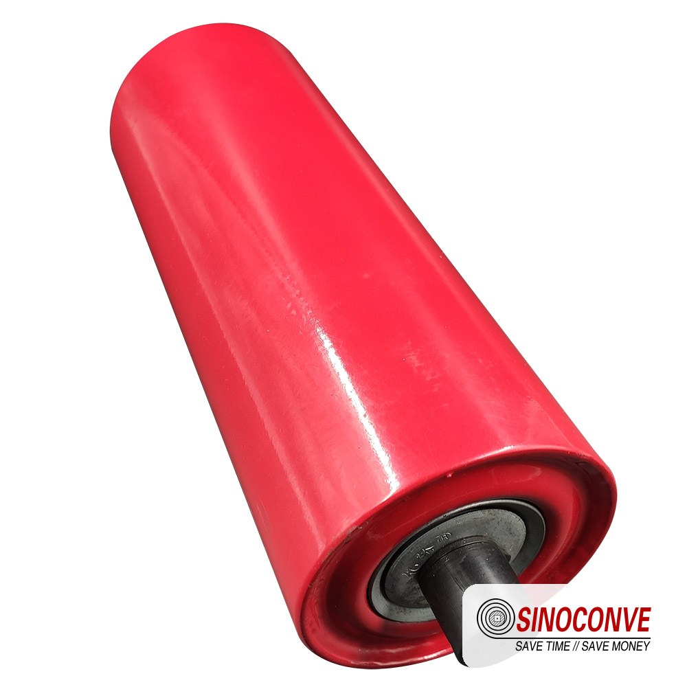
A finished roller is a tube, a shaft, two bearing housings and two seals. The tube is visible and easy to quote. The seals are not, and they are where service life is decided.
02The Roller Family by Position: Carrying, Return, Impact and Transition
Sort rollers by where they sit in the belt loop and the list becomes short and complete. Every conveyor, from a 500 mm quarry feeder to a 2,400 mm port loader, uses some combination of the types below, and the sizes we build for each of them are listed on our conveyor roller page.
Carrying and troughing idlers
The carrying rollers sit under the loaded belt, in groups of two, three or five inside a frame whose angle forms the trough. A three-roll set at 35° is the standard for belts from 800 mm to 1,400 mm. Five-roll sets and 45° troughs exist for very wide belts and tight transfers, and both cost extra belt edge stress. Shells run from 102 mm on light lines to 178 mm on heavy ore duty, with 127 mm and 152.4 mm the most common.
Spacing is set by the material, not by the drawing legend. Dense ore at 2.4 t/m³ wants 1.0–1.2 m; grain or wood chips tolerate 1.2–1.5 m. Section 06 shows how to check whether the pitch you inherited holds the sag inside limits.
Return rollers
Belt weight alone lands on the return strand, so return rollers are one shell size smaller and 0.5–1.0 mm thinner in the wall, at 2.4–3.6 m centres. What they do not escape is wear. Carryback stuck to the cover grinds the shell like sandpaper, which is why the return strand of a washed-sand plant destroys rollers faster than the carrying side ever does.
Impact rollers in the loading zone
Nothing on a conveyor is abused like the 2 m of belt under the chute. Impact rollers replace the bare tube with rubber rings, a rubber-covered shell, or discs on a reinforced shaft. The compliance spreads the point load over more belt and damps the rebound that throws fines around the skirt. Sets sit at 300–500 mm centres in the loading zone, with one more 1–2 pitches downstream as the bed settles. Diameters run 152–194 mm and shafts start at 30 mm. Our page on impact roller supply for loading zones covers ring hardness and drop-height maths.
Transition rollers
The transition zone is the short run between the pulley tangent point and the first full troughing set. Roll the belt from flat into 35° too quickly and the edges over-stretch while the centre stays slack; the result is edge cracking 300–500 mm in from each edge, usually inside 18 months. Transition rollers are carrying rollers in shallower 20° and 30° frames. Publicly quoted guidance in the CEMA tradition puts transition distance at 1.5–3 belt widths for fabric-carcass belts, so 1.5–3.0 m on a 1,000 mm belt. If your layout gives 600 mm, no roller specification will save the belt.
The family at a glance
| Type | Position in the loop | Shell / shaft band | What it must carry | Design point that decides life |
|---|---|---|---|---|
| Carrying (troughing) | Under the loaded strand, in 2-, 3- or 5-roll frames | 102–178 mm shell, 20–40 mm shaft | Belt mass plus material mass | Bearing size and seal stages at the fastest roller in the set |
| Return | Under the empty return strand | 89–152 mm shell, wall 0.5–1.0 mm thinner | Belt mass only, plus carryback abrasion | Surface wear from sticky or wet carryback |
| Impact (buffer) | Directly beneath the chute and skirt | 152–194 mm, rubber rings or discs, 30 mm shaft up | Lump energy plus full bed load | Ring hardness and shaft stiffness under shock |
| Transition rollers | Between pulley tangent and first full trough set | Fixed 20° or 30° frames, 127–178 mm | Belt mass plus material, at a shallow angle | Transition distance available in the layout |
| Training (self-aligning) | Every 30–50 m on both strands of a long conveyor | Pivoted carriage, 127–178 mm shells | Normal roller load plus a steering moment | Freedom of pivot, not the roller itself |
| Guide / side roller | Vertical or inclined at the belt edges, transfers and reversible lines | 50–89 mm shell | Edge contact force, intermittent | Mounting stiffness; side rollers that flex do nothing |
Table 1. The six position-based roller types that cover almost every bulk conveyor. Section 03 then covers the function-based variants — training, spiral and cleaning rollers — that earn their extra cost on specific problems.
03Rollers Chosen by Function: Tracking, Spiral and Cleaning Duty
Position tells you where a roller goes. Function tells you what shape it has. Three functional families earn their extra cost on specific problems, and all three are frequently fitted in the wrong place.
Self-aligning and friction-tracking rollers
A training idler is a short frame on a vertical pivot. Its rolls sit slightly forward of the pivot axis, so a wandering belt drags the leading side harder, the frame swings, and the resulting angle steers the belt back to centre. A friction-tracking version adds rubber-faced side rollers to raise the correction force at low belt loads. Both need the pivot free, the frame square to the belt at rest, and 5–10 mm of clearance to the structure.
Where they go: one set 10–15 m behind the head pulley on the carrying strand, then repeats at 30–50 m, plus a return-side set at roughly every third return position. Where they do not go: under the loading chute, inside the transition zone, or over a walkway where a swinging frame becomes a hazard. Our self-aligning roller comparison covers pivot versus friction types, and the rules in section 09 apply to all of them.
Spiral and helical rollers
Give a smooth steel tube a helical rib, or machine a shallow spiral groove into it, and you get a roller that cannot hold a layer of wet clay. The rib wipes the belt as it turns and the groove carries fines away from the seal line instead of pushing them in. Washed sand, filtered tailings and damp fertiliser are its natural duty. The penalty is a rougher contact patch and slightly higher drag, so it is the wrong choice on a clean granite circuit where a plain roller runs cheaper and lasts as long.
Rubber-disc cleaning rollers
A cleaning roller is a shaft carrying 15–20 mm rubber discs at 30–50 mm centres, sitting on the return strand a metre or so behind the head pulley, scraping what the primary scraper missed. Disc spacing is the design: too wide and material passes between the discs, too narrow and they pack and stop scraping. For 40 mm minus material, 40 mm spacing is a fair start; for fine filter cake, closer to 30 mm. These rollers add drag, so include them in the return drive calculation, and keep them away from belt that is still hot enough to soften the compound.
When the belt, the rollers and the scraper are quoted as a package they arrive together, which is easiest through a conveyor belt supplier who stocks both consumables.
04Shell Materials: Carbon Steel, Stainless, Polymer and Ceramic
The tube is the part everyone asks about, because it is the part you can see. It is also the part that least often causes a failure. Still, material choice drives both price and weight, and in corrosive or high-wear service it decides whether the roller reaches year three.
Carbon steel, the default
Cold-drawn or ERW seam-welded steel tube in 3.0–6.0 mm wall is the industry default, from 89 mm to 219 mm. Painted, or hot-dip galvanised where humidity is high, it gives the best stiffness per unit cost. For heavy ore duty we start at 4.5 mm wall and go to 6.0 mm on 194–219 mm shells in the loading zone. Straightness matters as much as wall: a tube with 1.5 mm of bow over 1 m pulses the belt at every revolution.
Stainless and polymer shells
Stainless 304 shells with stainless shafts and end caps are the answer in salt handling, fertiliser plants and food lines where washdown is routine. Grade 316 or duplex is reserved for chloride-heavy service such as seawater-dredged material; stainless still wears, and it costs 3–5 times a painted carbon steel tube. HDPE and UHMWPE sit at the other end: 2.5–4.0 kg for a 127 mm × 500 mm roller against roughly 11 kg for the steel equivalent. They resist acids, reduce noise and cause almost no belt wear. Their limits are temperature (softening above about 80 °C, so no hot clinker), impact, and load rating, which is a fraction of steel.
Ceramic and heavy-rubber covered shells
Ceramic tiles bonded to the shell answer one specific problem: a roller grooving in the same place because the trough bottom is permanently loaded with abrasive fines. The tiles are harder than the material and spread the contact patch, and we reserve them for the centre roll of a heavily loaded set. Rubber-covered shells are chosen for grip or noise rather than wear, and you will meet them on guide rollers and incline lines.
| Shell material | Temperature band | Corrosion | Relative cost index | Choose it when |
|---|---|---|---|---|
| Painted carbon steel | −20 to 80 °C | Poor without coating | 1.0 | Dry bulk, sheltered gallery, aggregate and cement |
| Hot-dip galvanised steel | −20 to 80 °C | Good in salt mist | 1.2–1.4 | Open stockyards, port quays, coastal plants |
| Stainless 304 | −40 to 120 °C | Very good in wet service | 3–5 | Salt, fertiliser, food lines, frequent washdown |
| Stainless 316 / duplex | −40 to 120 °C | Best in chloride | 5–8 | Sea-dredged material, brine and acid vapour |
| HDPE / UHMWPE | −30 to 80 °C | Good against most acids | 1.3–2.0 | Light duty, low noise, non-impacting, chemical plant |
| Ceramic tiled steel | −20 to 120 °C | As base steel | 4–7 | Grooving wear, one or two rollers only |
Table 2. Shell options compared on the two criteria that actually separate them: heat and chemistry. Cost index is relative to painted carbon steel.
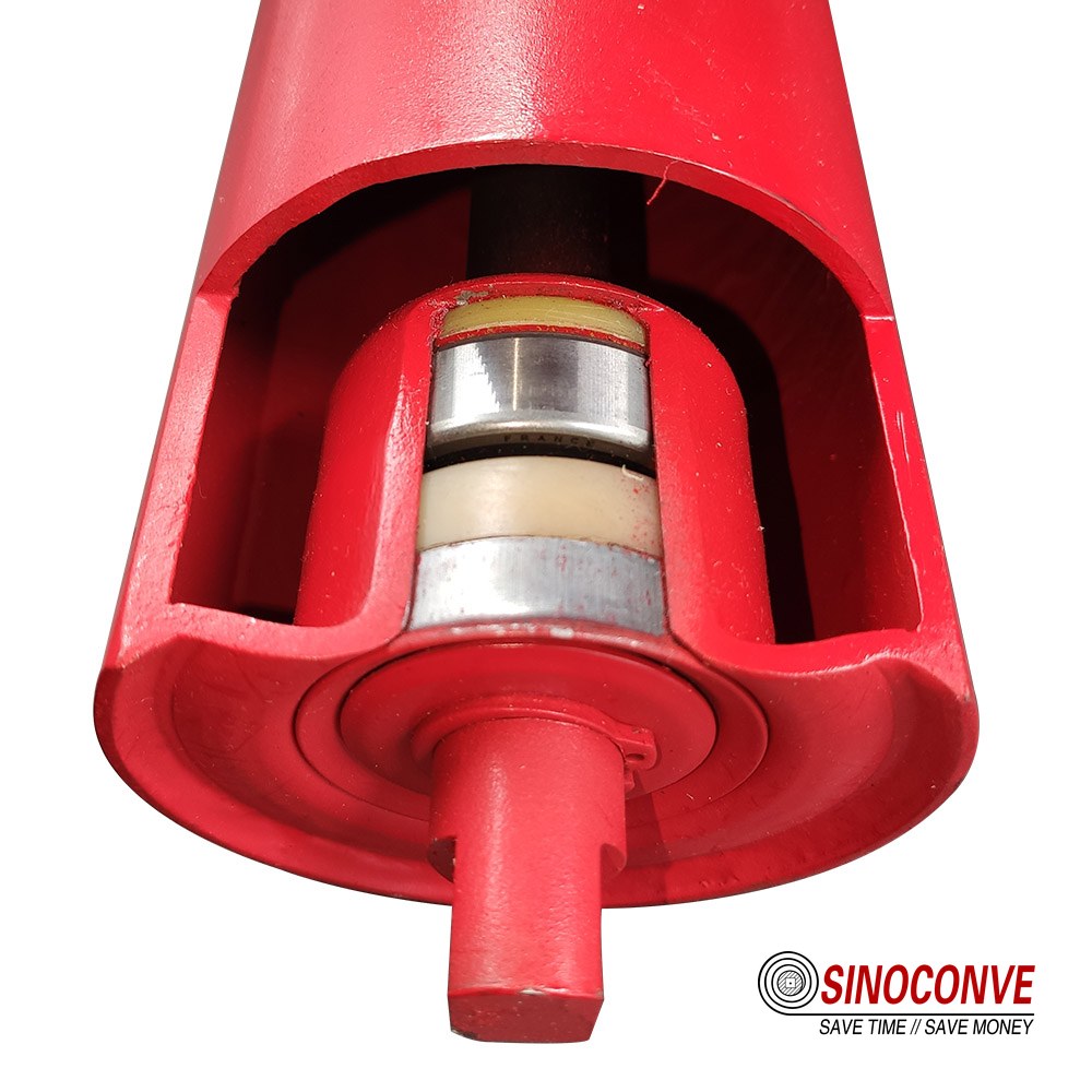
Rollers work in groups. Frame angle, pitch and shell size are one geometry, and changing any one of them moves load onto a different roller in the set.
05Bearings, Seals and Grease: Where Cheap Rollers Cut Corners
This is the section to read twice. Two rollers can have the same 152.4 mm shell, the same 25 mm shaft and the same paint, and one will run 45,000 hours while the other loses its bearings in 7,000. The difference is inside the end cap, and it is worth maybe 4% of the purchase price.
Ball bearings versus tapered roller bearings
A deep-groove ball bearing is the standard choice up to about 178 mm shell diameter. It carries radial load well, tolerates the small axial float a roller needs, and is cheap. Common bores in roller duty are 20, 25 and 30 mm, and we quote the bore, the clearance class and the shield type rather than a brand, because the housing and the seal matter more than the logo on the ring.
Tapered roller bearings appear where radial load is heavy and the shock is real: 194–219 mm shells in primary crusher discharge, transfer towers and run-of-mine loading zones. They take more load for the same bore but need proper axial end-float, and set loose they pound themselves apart. That is why they belong on rollers a competent workshop assembles, not on the cheapest line item in a tender.
The seal is the roller
Dust does not kill a bearing in one event. It grinds the grease into a lapping paste, the film breaks down at 60–90 °C, and the race surface spalls. A four-stage labyrinth beats a single lip every time: in cement mill feed or a coal bunker gallery, a plain 2RS contact seal gives up in 6,000–9,000 hours while a five-stage labyrinth with a grease-filled outer chamber in the same position passes 30,000. Look for at least three interlocking metal rings, a non-contacting gap of 0.2–0.5 mm rather than a rubbing lip, grease packed in the outer chamber as a dust trap, and a machined housing that holds the outer ring without walking. If a supplier cannot tell you how many labyrinth stages their roller has, they do not know, and that is the answer.
| Bearing / seal combination | Environment it copes with | Typical service band | Failure signature when it is wrong |
|---|---|---|---|
| Ball bearing, single contact lip seal (2RS style) | Dry, coarse, sheltered gallery | 6,000–12,000 h | Lip wears into a groove by month 10, dust track visible on the shaft seat |
| Ball bearing, non-contacting shield (ZZ style) | Clean indoor lines only | 4,000–8,000 h outdoors | Grease turns grey-black, free-run revolutions drop from 10 to 2 |
| Ball bearing, 4–5 stage labyrinth plus grease trap | Fine dust, slurry splash, washdown | 30,000–45,000 h | Usually the shell or shaft wears out first, not the bearing |
| Tapered roller, labyrinth, high-temp grease | Shock loading, run-of-mine rock, 120–150 °C zones | 20,000–35,000 h with correct end-float | Axial clearance opens, roller rattles when shaken by hand |
| Polymer housing with labyrinth, polymer shell | Corrosive, low load, quiet areas | 15,000–25,000 h | Housing deforms before the bearing fails; check rated load first |
Table 3. Bearing and seal combinations with the service bands we see in the field. Environment, not price, decides which row you need.
Grease, fill volume and temperature limits
A lithium-complex NLGI 2 grease with EP additives covers the majority of roller duty from −20 °C to +120 °C. Below about −25 °C the base oil stiffens enough that starting drag on a 152 mm roller can double, which shows up as belt slip at the head pulley on a cold morning shift. Cold stores, arctic yards and freezer-adjacent conveyors need a synthetic low-temperature grease, and that is a specification, not an upgrade to be negotiated away.
At the hot end, standard lithium grease oxidises and bleeds above roughly 120 °C. Clinker, sinter and foundry sand routes call for a polyurea or synthetic high-temperature grease rated to 150–180 °C, with FKM (fluorocarbon) seals rather than nitrile, because nitrile hardens and cracks in that band. Fill volume is the other half of the story: a roller is normally packed to 30–50% of the housing free volume. Too little and the labyrinth chamber stays dry; too much and the grease churns, raises drag and pushes the seal open.
Field note from our engineers: A port terminal replaced a full stringer of rollers on a coal export line three times in nine months and blamed the coal dust. We cut the end caps open on two of them. The shells were within 0.4 mm of new. The bearings held a gritty grey paste, and the labyrinth had three stages with no grease trap in the outer chamber, because the second tender had been decided on unit price alone. Same diameter, same shaft, same certificate of origin. Nine months of downtime came down to about 4% of the unit price.
Dust and water are the two enemies, and fine dust is the worse of the two because it travels. Our page on sealed rollers for fine dust goes deeper into labyrinth geometry and what to ask for in a drawing. If you are buying from a conveyor belt factory that also builds its own idlers, ask for the seal cross-section, not the seal name.
06Load Rating: How the Load on One Roller Is Calculated
Tonnes per hour is not a roller specification. It never has been. A conveyor pushes a distributed weight down into the trough, and the rollers underneath divide it up according to their geometry. Six lines of arithmetic settle the question, and they settle it straight away — whether the roller on the quotation is oversized, about right, or quietly being asked to carry twice what its rating allows.
The load equation
We start in weight per metre, because everything downstream is built on it. qB is the belt's own mass, and it does not have to be guessed at. A 1,000 mm wide EP belt with a 6 mm top cover, a 2 mm bottom cover and a four-ply carcass lands at roughly 15 kg/m. The material is a different story — qM comes out of the throughput figure, as qM = Q ÷ (3.6 × v), with Q in t/h and v in m/s. After that, two multiplications. Gravity turns the sum into a line load in N/m, and roller pitch turns that line load into the weight one carrying set has to hold.
F_set = (qB + qM) × 9.81 × S × k
S is the carrying roller spacing in metres. k is our dynamic factor, and it exists for the messy parts a clean formula would rather ignore — belt flexure between the rolls, the thump of material landing, and the plain fact that no conveyor runs perfectly smoothly. On gentle, well-chuted duty we take k = 1.1. The default is 1.15. Under a loading zone that sees 300 mm lumps, we go to 1.25.
A worked example you can copy
Our example runs on a 1,000 mm conveyor with 35° three-roll troughing sets. It carries 1,200 t/h of granite at a bulk density of 1.6 t/m³. The belt runs at 2 m/s, and the carrying rollers are pitched at 1.2 m.
Run the material first. qM = 1,200 ÷ (3.6 × 2) gives 166.7 kg/m, and dividing that by the 1,600 kg/m³ bulk density gives a filled section of 0.104 m². For a 1,000 mm belt in a 35° trough that figure looks right. Now the belt itself. With qB = 15 kg/m the line load totals 181.7 kg/m, which is 1,782 N/m.
Per carrying set the load works out at 1,782 × 1.2 = 2,139 N, and applying k = 1.15 lifts it to 2,460 N. How that load splits is geometry, not preference. With equal-length rolls at 35°, the centre roll collects about 65% and each side roll about 17.5% — 1,599 N on the centre, 430 N on each side. Apply the usual 1.5 service factor to the centre roll and the roller you specify needs a rating near 2.4 kN.
That single number is the whole exercise. A new buyer opens the bearing catalogue, sees a capacity several times larger than 2.4 kN, and walks away convinced that any roller in this size will do. It will not. The rated load a manufacturer publishes is fixed by the housing, by the shell stiffness and by the seal at an intended L10 life; the bearing is only one of those four contributors. Most manufacturers publicly quote a heavy-series 152.4 mm roller on a 25 mm shaft with labyrinth sealing in the 2.5–3.5 kN band. Drop a light-series equivalent into the same frame and it works at its limit from day one.
| Symbol | Quantity | Value in the example | Where you get it |
|---|---|---|---|
| B | Belt width | 1,000 mm | the layout drawing |
| Q | Throughput | 1,200 t/h | Process duty, not nameplate |
| v | Belt speed | 2.0 m/s | straight off the drive datasheet |
| ρ | Bulk density | 1.6 t/m³ | Measured, not assumed from a table |
| qB | Belt mass per metre | 15 kg/m | Belt datasheet for this width and cover |
| qM | Material mass per metre | 166.7 kg/m | Q ÷ (3.6 × v) |
| S | Roller spacing | 1.2 m | Your call, see sag check below |
| k | Dynamic factor | 1.15 | 1.1 calm duty, 1.25 under a chute |
| F_set | Load on one carrying set | 2,460 N | (qB + qM) × 9.81 × S × k |
Table 4. Our working sheet for the example above, with the source of every entry written beside it. Put your own figures in the last column and read the bottom row — change any single input and the roller has to change with it.
Trough angle changes both the area and the split
Watch the trough angle, because it enters the calculation twice and both entries are easy to overlook. A deeper trough holds a bigger load area at the same belt width, which raises the material mass per metre. Then it does something less obvious — it pushes a larger share of that mass onto the centre roll.
| Trough angle | Load area on a 1,000 mm belt | Centre roll share | Side roll share each | Where it is used |
|---|---|---|---|---|
| 20° | about 0.085–0.09 m² | 40–45% | 27–30% | Narrow belts picking up light material, and the transition frames at both ends |
| 30° | roughly 0.09–0.10 m² | 50–55% | 22–25% | Where most general-purpose belts sit, 800–1,000 mm wide |
| 35° | 0.10–0.11 m² | 60–65% | 17–20% | The bulk standard — 1,000–1,400 mm belts, three equal rolls, nothing clever |
| 45° | 0.115–0.13 m² | 65–70% | 15–17% | Deep-trough upgrades and tight transfers on high-capacity lines |
Table 5. How we read this one. Find the angle you are running, then look at the centre share before you trust the side rolls. Typical figures for equal-roll three-roll sets — recalculate for your own geometry.
Spacing, sag and the belt you are trying to protect
Spacing is the lever almost nobody touches, and it moves two things at once — the load on the roller and the sag in the belt. Sag is the classic check, and the formula is y = w × S² ÷ (8 × T), in which w is the line load in N/m and T is the belt tension at that point. Hold the result under 2% of the spacing; on a thin-cover belt, or in a low-tension section, we aim for 1%.
Put the example under a modest 40 kN of tension and the pattern shows up quickly. At S = 1.2 m the sag works out at 1,782 × 1.44 ÷ 320,000 = 8.0 mm, which is 0.67% of the pitch. Open the spacing to 1.5 m and it grows to 12.5 mm, with the centre roll load climbing to about 2.0 kN. At 2.0 m the sag reaches 22.3 mm. Stretch to 3.0 m on a low-tension section and it blows past 150 mm — that belt spills at every frame, and its cover cracks over the trough line inside a season.
Return rollers have an easier job, because the belt is all they carry. The 15 kg/m becomes 147 N/m, and at 3.0 m pitch under the same 12 kN tension the sag is only 13.8 mm. Remember that cover mass is the qB sitting in every line of the equation. That is why the industrial conveyor belt chosen for a crusher line and the roller pitch under it are really one decision, split across two purchase orders.
07Shell Diameter, Rotational Speed and Bearing Life
Most buyers read shell diameter straight off a catalogue table and match it against the belt width. That does produce a roller that works. It also buries the most useful relationship in this article — at a fixed belt speed a bigger shell turns more slowly, and a slower roller lasts longer.
Why diameter sets speed
Rotational speed follows from surface speed and nothing else. The relation is n = v ÷ (π × D), with n in revolutions per second and D in metres. On a 2 m/s conveyor a 127 mm shell turns at 301 rpm; fit a 152.4 mm shell to the same conveyor and it turns at 250 rpm. Push the belt to 4 m/s and those two rollers spin at 601 rpm and 501 rpm. The belt is indifferent to all of this. The seals and the grease are not.
Hold on to one number. On a 4 m/s conveyor, anything below about 133 mm spins faster than 570 rpm, and that is the region where a single-lip seal runs warm and a bearing short on fill volume throws grease off the cage. On a high-speed line a larger shell buys you more than a better seal ever will, and the reason is arithmetic rather than metallurgy.
| Shell OD | 1.0 m/s | 2.0 m/s | 3.0 m/s | 4.0 m/s | 5.0 m/s |
|---|---|---|---|---|---|
| 89 mm | 215 rpm | 429 rpm | 644 rpm | 858 rpm | 1,073 rpm |
| 102 mm | 187 rpm | 374 rpm | 562 rpm | 749 rpm | 936 rpm |
| 127 mm | 150 rpm | 301 rpm | 451 rpm | 601 rpm | 752 rpm |
| 152.4 mm | 125 rpm | 250 rpm | 376 rpm | 501 rpm | 626 rpm |
| 178 mm | 107 rpm | 215 rpm | 322 rpm | 429 rpm | 537 rpm |
| 194 mm | 98 rpm | 197 rpm | 295 rpm | 394 rpm | 492 rpm |
| 219 mm | 87 rpm | 174 rpm | 261 rpm | 349 rpm | 436 rpm |
Table 6. Handy when somebody asks whether a faster belt needs a bigger shell. Speeds for the shell sizes we build most; halve them and bearing life roughly doubles, which is the cheapest upgrade on a fast line.
The trade-off at high belt speed
Diameter is not free. A 219 mm shell of the same wall thickness weighs roughly twice what a 152.4 mm shell does, so frames, brackets and structure have to grow with it. There is a payback, though. The belt bends less over a large roller, so on a long conveyor part of the extra cost comes back as drive energy. For a 3 km overland conveyor at 4.5 m/s we would argue for 178–194 mm carrying rollers and live with the heavier frame. On a 40 m in-plant conveyor at 1.2 m/s? 127 mm is the sensible answer.
Then there is the shaft, which is a separate decision. Shell diameter protects the bearing; shaft diameter protects the bracket. As starting points, we work from 20 mm shafts with shells up to 102 mm. Across 127–152 mm we step up to 25 mm, and 30 mm carries 178 mm. Anything on 194–219 mm heavy-series rollers in a loading zone gets 40 mm. Clamping counts for as much as the diameter does. A roller that rattles in a worn bracket hammers its own bearings, and no shaft size will rescue it.
Cost is not a good reason to under-specify here. Where you are buying volume and comparing a wholesale conveyor belts and idler package, the honest comparison is cost per 10,000 hours of service rather than cost per piece. A 178 mm roller that lasts twice as long at 1.6 times the price is the cheaper one. Partners who hold idler stock locally tend to put this case well, because they see the repeat orders.It holds whether they are a conveyor belt distributor working aggregate accounts or a specialist idler house. And where belts and rollers fail together, price the rubber conveyor belt alongside the roller, so the whole strand is designed at once.
08Life Expectancy and the Four Ways a Roller Dies
Roller life is bearing life, right up to the moment it is not. Run the arithmetic once and you will see why a single bad month of dust can cost more than the original purchase order did.
The bearing life calculation, done once
Basic rating life for a ball bearing is L10 = (10⁶ ÷ (60 × n)) × (C ÷ P)³ hours, where C is the bearing dynamic capacity and P is the load actually carried. Take a 152.4 mm roller whose bearings are rated 14 kN, running at 250 rpm under the 1.6 kN load we worked out in section 06. C ÷ P = 8.75, so the cubed load term is 670; the speed term is 1,000,000 ÷ 15,000 = 66.7. Multiply the two and L10 lands near 44,700 hours. That is where the 40,000-hour figure quoted in this article comes from.
Now double the load, to 3.2 kN. That is what a roller sees when the belt is overloaded, when the trough angle is wrong, or when it sits under a spillage pile. C ÷ P falls to 4.375 and the cubed term to 83.7. L10 drops to roughly 5,600 hours. A 17% rise in belt loading can take 87% of the bearing life with it. Speed is linear. Load is cubic. When a roller dies early, check the load before you blame the bearing.
The four failure modes, in order of frequency
Seal failure leads this list by a wide margin, and the dust that gets past the seal is what does the damage. Bearing seizure comes second. In most cases it is simply the end of that same process. Shell wear-through is third, and it announces itself as a hole or a knife-edge groove in the trough bottom. The odd one out is out-of-round or excessive run-out, the only mode here that hurts the belt rather than the roller. Set a roller turning 1.5 mm out of true and it hammers the cover on every revolution, opening cover cracks directly above itself.
| Failure mode | What you see | Field measurement | Action threshold |
|---|---|---|---|
| Seal failure, dust ingress | Gritty sound when you spin it by hand. There is usually a dust ring on the shaft seat, and the grease has turned grey-black | Count hand spin revolutions after a firm push | Under 6 turns on a 152 mm roller and the bearing is contaminated |
| Bearing seizure | A polished flat on the shell and a smoke smell. The cover directly above is scorched | Point an IR gun at the shell surface | More than 40 °C above ambient — a sound roller sits 8–20 °C above |
| Shell wear-through | A visible groove at the trough bottom | Wall thickness, read with an ultrasonic gauge or calipers at the wear line | Replace below 60% of nominal wall |
| Out-of-round / run-out | Belt pulsation and a rhythmic slap. Look for cover cracks directly above the roller | Radial run-out against the shell, dial gauge | 0.5 mm is good. 1.0 mm is the point to pull it |
| Bracket and shaft-end wear | The roller rattles in the frame. Flats are rounded off and you can feel steps between frames | Feeler gauge, shaft flat to bracket seat | Any perceptible rock. A loose roller hammers its own bearings |
| Excess drag torque | Drive current creeps up, and the belt tracks to one side on a mixed stringer | Spring scale on the shell OD, arm length recorded | A new roller reads under 0.5 N·m; above 1.5 N·m, reject it |
Table 7. Six checks and the go / no-go limits we carry. Run them as a route down the strand rather than a campaign, and almost every roller that is about to fail will show itself.
Treat those checks as a routine rather than a campaign. Five minutes down the return strand with an IR gun and a dial gauge will find the two rollers that matter out of four hundred. A seized roller drags on the belt as well, and you see it in the drive current and in uneven wear across the head pulley lagging. Where the material is combustible dust, this stops being a maintenance annoyance and turns into a genuine ignition risk.
Field note from our engineers: A clinker line called us in because rollers were dying at around 4,000 hours, against the 30,000 they had budgeted. The rollers were not the problem. Their return strand was carrying a 40 mm layer of hot carryback, and the shell under it read 145 °C with 31 °C at the drive-end cap, standard lithium grease bleeding out of the high side. We moved the primary scraper 150 mm closer to the head pulley, then fitted high-temperature grease and FKM seals on the first four return positions. The next set ran past 20,000 hours. Measure shell skin temperature before you blame the roller supplier.
The same site gave us two drive-side belt failures, both caused by heat radiating off that clinker chute. A hot zone is a zone-wide problem, not a roller problem. We build idlers and we supply the drive side too, as a transmission belt manufacturer and a V-belt manufacturer, so we see it from both ends. The fix usually sits in the layout rather than in the compound.
09Installation and Alignment: Setting Rollers So They Stay Set
Most "bad" roller complaints we investigate turn out to be installation complaints. The roller is within tolerance and the frame it sits in is not square, not level, or not on the belt centreline. A frame skewed by 0.5° is 8 mm out over a 1,000 mm width, and 8 mm of skew on a set of carrying rollers is enough to steer a belt off the pulley. Aligning rollers quickly is a sequence, not a talent, and it is worth running against a known-good steel and polymer idler range rather than against whatever is currently in the frame.
Align in the right order
Work from the structure outward. Check the head and tail pulleys first: both square to the belt centreline, shafts level to within 0.5 mm per metre across the width. Then the stringers, because a bent stringer makes every frame above it wrong. Only then set the roller frames, and touch the training idlers last. Teams that start on the training idlers are chasing the symptom, and the belt runs off again as soon as the load changes.
Set frames from a single datum. Run a taut wire or a laser line down the top face of each stringer, square every frame to that line, then check the diagonals across the frame: they should match within 3 mm on a standard frame. Do not rely on the previous frame being right.
How the belt responds to a skewed roller
The classic rule of thumb is that the belt moves toward the end of the roller advanced in the direction of belt travel. If a belt runs off to the left, advance the left-hand end of the offending carriage by 3–5 mm in the direction the belt moves, then watch one full belt revolution before adjusting again. Chasing it with bigger moves is how a tracking problem becomes a tracking loop.
Two cautions. Align with the belt running at normal load, because an empty belt tracks differently and it is the loaded belt that spills. And check the return strand before you touch the carrying side; a belt dragged sideways by a badly set return roller will never track properly, whatever you do upstream.
Tolerances worth putting on the work order
| Setting | Target | Reject | What happens if you ignore it |
|---|---|---|---|
| Frame squareness to belt centreline | within 0.5° (±2 mm over 1 m) | over 1.0° | Belt steers off, edge wear on one side only |
| Height of trough bottom, adjacent frames | within 1.5 mm | over 3 mm | Belt bounce, cover fatigue above the high frame |
| Trough angle, left versus right side roll | symmetric within 1° | over 2° | Material piles to one side, then the belt follows |
| Frame pitch along the conveyor | within 3 mm of nominal | over 10 mm | One roller overloaded, sag uneven, belt humps |
| Training idler pivot clearance | 5–10 mm free all round | Binding or shimmed flat | A training idler that cannot pivot is a plain idler with extra cost |
| Free rotation of every roller | 8–10 hand-spin revolutions | under 5 | Localised drag, belt hunts toward the freer side |
Table 8. Settings we write into installation work orders. Everything here is cheaper to check with a level, a wire and a tape than to diagnose after the belt has run off.
Field note from our engineers: A quarry had fitted three training idlers along a 320 m conveyor and the belt still ran 60 mm off centre at the head. All three pivots were shimmed solid against the frame, because a rigger had packed them to stop them rattling, so they were doing nothing except adding weight. We cut the shims, corrected one stringer that was 14 mm off line over 20 m, and the belt centred itself in two passes. Total parts used: none. It is the cheapest fix in this article and the most common.
10What Different Industries Ask of a Roller
The same 152.4 mm steel roller is a ten-year component in a covered grain gallery and a nine-month consumable in a primary crusher discharge. Industry sets the environment, and the environment sets the specification. Five sectors account for most of what we ship.
Mining and quarrying
Coarse, sharp, dense and unpredictable. Rock up to 600 mm falls 2–4 m onto the belt, so impact rollers with 10–12 mm rubber rings and 30–40 mm shafts carry the first 2 m at 350 mm centres. Downstream, 152–178 mm heavy-series rollers at 1.0–1.2 m pitch take line loads above 250 kg/m. Granite dust travels through a single lip, so on a quarry conveyor system we specify five-stage labyrinth sealing and a 4.5 mm minimum wall as standard.
Cement, lime and clinker
Heat, abrasion and very fine dust together. Clinker leaves the cooler at 100–180 °C, and return-strand skin temperatures of 120–150 °C are normal. High-temperature grease and FKM seals are not optional; nitrile hardens and cracks within a season. The local wear pattern is a polished groove along the trough line, which is where a ceramic-lagged centre roll earns its price.
Ports and bulk terminals
High capacity, continuous duty, salt air, wet cargo. Shiploaders and stackers run 2,000–4,000 t/h over 1,600–2,200 mm widths at 3.5–5.0 m/s, which puts 178–219 mm shells on the carrying strand at 350–500 rpm. Everything is protected against corrosion: galvanised frames and end caps, splash-rated sealing. A terminal cannot stop a shiploader for one roller, so monitoring pays here more than anywhere. Our notes on rollers and pulleys in port systems cover the detail.
Power generation and heavy industry
Coal, limestone and ash bring fire risk along with the dust. Dust-tight rollers in a coal handling plant are partly an ignition control measure: a seized roller is a hot surface in a flammable atmosphere, and tight sealing also keeps the fuel away from the bearings. Ash conveyors are abrasive and often wet, which pushes the specification to thicker walls and cleaning rollers.
Agriculture, food and packaging
Lower loads, tighter hygiene rules. Grain and feed conveyors run 89–127 mm rollers at wide spacing, where the drivers are damp corrosion and dust ratings rather than load. Food and packaging lines go to stainless or polymer shells with washdown-tolerant seals on much lighter structures, which is where polymer wins outright: no rust, less noise, no marking. On those lines the roller and a PVC conveyor belt are usually specified as a pair.
| Industry | Dominant threat | Carrying shell / wall | Seal and grease requirement | Typical carrying pitch |
|---|---|---|---|---|
| Mining and quarrying | Impact, coarse abrasion, rock dust | 152–178 mm, 4.5–6.0 mm | 4–5 stage labyrinth, EP grease | 1.0–1.2 m, 350 mm at the chute |
| Cement and clinker | Heat, fine dust, groove wear | 152–178 mm, 4.0–5.0 mm, ceramic on centre roll | High-temp grease to 150–180 °C, FKM seals | 1.0–1.2 m |
| Ports and terminals | Salt air, wet cargo, continuous speed | 178–219 mm, 4.5–6.0 mm galvanised | Splash-resistant labyrinth, marine-rated coating | 1.0–1.3 m |
| Power and ash handling | Combustible dust, wet ash, abrasion | 127–178 mm, 4.0–5.0 mm | Dust-tight labyrinth, non-sparking consideration | 1.0–1.5 m |
| Aggregate and sand washing | Carryback, wet fines, silicate abrasion | 127–152 mm, 4.0 mm, spiral return rollers | Water-resistant labyrinth, cleaning rollers upstream | 1.2 m carrying, 3.0 m return |
| Agriculture and food | Damp corrosion, hygiene, washdown | 89–127 mm, stainless or polymer | Food-grade grease where contact is possible | 1.2–1.5 m carrying |
Table 9. Industry profile by threat, not by product line. Read your row, then check the seal column twice.
11Ten Roller Buying and Application Mistakes
These are the ten we see repeatedly, ordered roughly by how much money they cost. Several are decisions made in a tender document rather than on site, which is why they survive for years.
The ten, with the fix beside each one
| Mistake | Why it costs money | What to do instead |
|---|---|---|
| Buying on shell diameter and price | Two rollers at the same 152.4 mm outside diameter can differ fivefold in life | Ask for the labyrinth stage count and the seal cross-section |
| Mixing drag torque along one stringer | The belt hunts toward the free-running side, so a crew then adjusts frames that were never wrong | Replace in contiguous groups, not one roller at a time |
| Impact rollers in the wrong place, or none at all | Fitting rings along the whole conveyor wastes money; fitting none under a 3 m drop destroys the cover in weeks | Measure drop height, then place impact sets under the chute only |
| Using a roller where a pulley is needed | An idler is not built for belt tension or drive torque; we watched one shaft fail in two shifts | If it takes tension or transmits power, specify and lag a pulley |
| Ignoring the lubricant temperature window | Lithium grease stiffens the start-up at −30 °C and oxidises above 120 °C, cracking nitrile seals | Specify grease and seal elastomer by ambient range, in writing |
| Copying roller spacing from an old drawing | Move from 1.2 to 2.4 t/m³ material and the line load doubles, the centre roll doubles, the sag check fails | Re-run the section 06 calculation whenever the material changes |
| Mixing shell diameters in one frame | A 12.7 mm step hammers the belt every revolution and starts a cover crack above the high frame | Keep one stringer dimensionally consistent |
| Specifying by tonnes per hour and forgetting lump size | Throughput sets belt mass; lump size and drop height set impact energy, a different number entirely | Send both figures with the enquiry, or expect a wrong roller |
| Deepening the trough angle to cure spillage | 45° puts 65–70% of the load on the centre roll and raises edge tension, so both fail early | Fix the skirt, the chute or the loading centring instead |
| Running to failure because nothing is measured | Temperature and drag both rise weeks before seizure, and the first warning is then a scorched belt | An IR gun pass once a month beats fixed-interval replacement |
Table 10. The ten mistakes, ranked by what they cost. Nine of the ten are specification decisions, not maintenance decisions.
Mistake 6 is the one that quietly ruins belts. A roller sold as standard duty is standard for a 1.2 t/m³ material; if your ore runs at 2.4 t/m³, the same part works at double its rated load from day one, which by the cubic relationship in section 08 is an eighth of the bearing life. Nothing in the purchase order will look wrong.
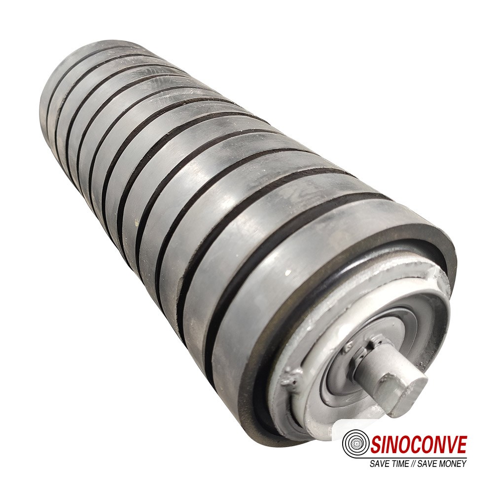
Rollers are consumables made in batches. That is exactly why the seal drawing, not the shell diameter, is the document to keep on file between orders.

12Conveyor Roller Questions We Get Every Week
Is a conveyor roller the same thing as an idler?
In normal plant usage, yes. Roller and idler both describe the free-turning cylinder that supports the belt. Pulley is the word that means something else, and it means the driven or redirecting drum at the ends of the conveyor.
How do I know when a roller has failed?
Three checks, in this order. Spin it by hand: a sound 152 mm roller coasts for 8–10 turns, a contaminated one stops in two or three. Shoot it with an IR gun: a healthy roller runs 8–20 °C above ambient, a failing one 40 °C or more. Then look for a polished flat spot. Any one of the three justifies pulling it.
How many rollers does one conveyor need?
Count frames, not rollers. Divide the centre distance by the pitch: a 320 m conveyor at 1.2 m carrying pitch takes about 267 three-roll sets, roughly 800 rollers on the loaded side, plus around 105 return rollers at 3.0 m pitch. That excludes the impact zone, where four or five closer frames replace one.
Can I fit a bigger roller into an existing frame?
Sometimes, and it is worth asking before you assume. Frame pockets, bracket centres and shaft flats are sized for one shell diameter. Going from 127 mm to 152.4 mm usually means new frames, and the extra 25 mm raises the belt line, which changes the belt path at the head pulley.
Steel shell or polymer shell?
Steel, unless the environment says otherwise. Steel gives four to five times the load rating and far better impact behaviour for a similar price. Polymer earns its place in salt, acid and food-grade service, and on light conveyors where weight, noise and belt marking matter more than capacity.
Do return rollers need a different specification?
Different, but not necessarily cheaper. Return rollers carry belt weight only, so a thinner wall and a wider pitch are fine. The catch is carryback: a wet or sticky return strand wears faster than the loaded side, and that is where cleaning rollers and spiral shells belong. They also run hotter on a hot strand.
Why do rollers fail in the loading zone first?
Because a falling lump delivers its energy over a few square centimetres in a few milliseconds. Spacing at 300–500 mm, rubber-ring impact rollers and a 30 mm shaft are the standard answer. If the chute throws material onto the belt edges, no roller will survive there, so look at the chute first.
What actually stops fine dust reaching the bearings?
Multiple labyrinth stages and a grease-filled outer chamber, not a single rubber lip. Ask for the seal cross-section and count the stages. Four or five stages with a 0.2–0.5 mm non-contacting gap is the difference between 8,000 and 35,000 hours in a cement gallery, and it is the cheapest specification line you can add to a roller purchase.
How often should rollers be inspected?
Monthly on a two-shift plant, weekly on a loading zone or a washed-material return strand. The route is short: hand spin, IR gun, look for flats. The savings come from catching the two rollers that are about to seize, not the one that already has.
13Related Products You May Need
| Product | What it is | Typical duty |
|---|---|---|
| Conveyor roller | Steel, stainless and polymer idlers, 89–219 mm, carrying, return, impact and training types | Bulk conveyors in mining, quarry, cement and ports |
| Rubber conveyor belt | EP and NN fabric-cored belt with abrasion, heat, oil and flame-resistant covers | Primary and secondary conveying duty |
| EP rubber conveyor belt | Polyester-nylon carcass for high tension and long centres | Overland and high-capacity lines |
| Heat resistant conveyor belt | Covers rated for clinker, sinter and cement kiln feed | Cement, lime and foundry plants |
| PVC conveyor belt | Lightweight belt for unit handling and washdown lines | Parcels, food packing, warehousing |
| V-belt | Wrapped and raw-edge friction belts for the drives on the same plant | Crusher, fan and pump drives |
| Full product catalogue | Every belt, idler and drive belt family we build, with the grade options | Start here when you are specifying a whole line |
14Related Blog Posts
- Conveyor idler roller guide: how to choose the right one — the selection sequence, once the theory above is settled.
- Self-aligning roller: choosing the right conveyor solution — pivot geometry and where a training idler actually works.
- Sealed conveyor rollers for fine dust
- Impact roller supply for loading zones — ring hardness, drop height and how close to the chute they go.
- Steel conveyor rollers: heavy-duty selection guide
- Steel conveyor belt roller performance under pressure
- Conveyor rollers in heavy-duty belt conveyor systems
- Corrosion resistant conveyor roller supplier — salt, acid and washdown duty.
- Conveyor roller and pulley supply for port systems
- Conveyor roller manufacturer for mining bulk handling
- OEM conveyor idler manufacturer for projects
- Rubber conveyor belt ultimate guide (2026): types, grades and how to choose
- EP conveyor belt tracking guide — belt-side fixes that pair with the roller settings in section 09.
- Conveyor roller selection guide for reliable material handling
- Heat resistant conveyor belt for cement plant clinker handling