
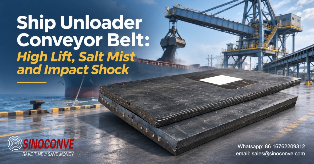
A grab unloader does not feed a belt so much as drop a load onto it. A 25 cubic meter grab opened above the hopper releases eighteen tonnes in under two seconds, and the boom belt underneath takes that energy across two or three meters of running surface. Everything behind that point is designed around the fact that the first meters of the machine get hit for a living.
A hundred meters away, the same belt hangs in open coastal air. Chloride settles on the cover overnight, the washdown water runs brackish, and salt spray reaches pulley faces and idler shafts that nobody can touch without a crane and a permit.
We supply belting into terminals like that, and the calls we get are rarely about tensile strength. They are about impact, edge damage and water. Three mechanisms, one belt. What follows is how they interact, and what to write into a specification so the belt you order matches the duty the machine actually imposes. If you are still comparing terminal layouts, start from our conveying setups grouped by industry and work down from there.

01Marine Terminal Operating Conditions: Free Fall Shock, Marine Atmosphere and Non-Stop Turnaround
Coastal bulk terminals run on a berth window. A Panamax vessel is hired by the day, the unloader is the only machine that can empty it, and the belt on the boom is the single component between the terminal and a demurrage claim. That commercial fact shapes every technical decision downstream of it.
What a Grab Discharge Does in Two Seconds
Grab capacity on a mid-size unloader runs from 12 to 30 cubic meters, and the payload depends entirely on what is being dug. Coal at roughly 0.85 tonnes per cubic meter gives a light grab; iron ore fines at 2.2 or more turn the same bucket into a 45 tonne hammer. The drop from an open grab to the hopper floor is commonly between 10 and 20 meters, which puts the material at the impact point at around 17 meters per second. Momentum of that order does not care about your belt tension.
What fails first is almost always local. The cover indents, the rubber under the impact point thins, and a cord or a ply takes a load it was never designed to carry. On a steel cord belt you find it later as a bulge or a single broken wire; on a fabric belt the ply separates quietly until the splice lets go. Both are consequences of the same event: a point load arriving faster than the support structure can spread it.
The fix is structural before it is chemical. Cushion idlers at 300 to 400 mm pitch across the first five meters of the loading zone, a skirt that seals without pinching the edge, a rock box or dead bed of material to absorb the first strike, and a top cover thick enough to be a wear item rather than a structural one. Chute geometry matters as much. A grab that dumps against the direction of belt travel doubles the relative velocity and the damage with it.
The Marine Atmosphere Is a Slow, Permanent Load
Salt fog is not a chemical attack on rubber in the way that hot clinker or diesel is. The compound survives contact with sodium chloride reasonably well. The trouble is the interface. Chloride deposits are hygroscopic, so a salt film on the cover stays damp through the night even when the air is dry, and condensation cycles on a belt that cools after a shift put free water into every cut, every exposed fabric edge and every splice step.
Once water reaches a brass-coated steel cord, the coating corrodes and the rubber-to-brass bond goes with it. The cord does not lose strength on day one. It loses grip, and then the belt works the wire, and then you have a separation that runs a meter a month until the belt is scrap. This is why we specify a closed edge and a sealed splice on any coastal machine, and why we ask what the washdown water is.
Field note from our engineers: At a coal terminal we were asked to look at a boom belt fourteen months into service. Eight millimeter top cover, 1,800 mm wide, running 3.2 m/s. At the hopper the cover measured 2.5 mm; forty meters down the boom it still measured 6 mm. The belt had not worn out, it had been beaten out over four meters of travel. The replacement went in at 12 mm over the first eight meters and 8 mm for the rest of the run, spliced at the transition. That belt is still on the machine.
Why the Terminal Cannot Stop for a Belt Change
An unloader in a busy berth may log 5,000 to 7,000 running hours a year, and the belt change has to fit between vessels. There is no quiet Sunday. A hot splice on a 1,600 mm steel cord belt takes a full shift including the cure, and a full belt replacement on a boom is a two or three day operation with cranes and rigging. Plan for three to four years of service and keep a spare roll on site, because the alternative is a week of waiting for a container.
02Machine Anatomy: Boom Conveyor, Traveling Gantry, and Incline Jib Feeds
A ship unloader is not one conveyor. It is four or five short ones stacked on a moving structure, and each of them sees a different load. On the berths that handle coal, ore and fertilizer in bulk, buyers who treat the machine as a single belting requirement end up with one construction everywhere: too heavy at the tip, too light at the hopper, and impossible to splice in the spaces where the splice has to live.
The Boom and Jib Run: Long, Exposed and Unforgiving
The boom conveyor carries screened material at steady rate once the hopper has done its work, but it is the most exposed belt on the machine. It luffs, it slews, and it hangs over water for most of its length. Wind loading on an empty belt is real, and a belt that is under-tensioned for its width will lift off the troughing idlers between supports on a gusty day.
Widths on this duty sit between 1,200 and 2,000 mm, belt speeds between 2.5 and 4.0 m/s, and terminal capacities from 1,000 to 3,000 tonnes per hour. An industrial conveyor belt sized for those figures is carrying a high linear load on a relatively short center distance, which pushes you toward a stiff carcass and a take-up with limited travel. That combination is where troughability and splice thickness start to argue with each other.
Transfer Points: Where the Machine Shows Its Weakness
Between the boom and the incline jib there is always a transfer: a chute, a dribble chute, sometimes a small belt feeder. Material arrives with vertical velocity and leaves with horizontal velocity, and the change happens in under a meter. This is the second impact zone on the machine and the one most often forgotten, because it is buried inside the structure where nobody watches it.
We look at three things at every transfer. The drop height, which should be under 1.5 m wherever geometry allows. The angle of impingement against the receiving belt, which should be within 15 degrees of the direction of travel. And the clearance under the chute lip, which needs enough room for the splice to pass without contact. A splice that clips a chute lip twice a minute will fail in weeks, and the belt gets the blame.
| Conveyor section on the ship unloader | Dominant load that the section carries | Belt construction we normally propose here | What fails first when the section is under-specified |
|---|---|---|---|
| Hopper receiving belt directly under the grab discharge point | Repeated point impact from falling grab loads of mixed lump size | Steel cord carcass with twelve millimeter cover and a cushion impact bed | Cover punching through to the cord within the first two years |
| Boom conveyor running out over the vessel hatch | Steady high tension plus wind, salt spray and long exposure | High tensile EP or steel cord with sealed edges both sides | Edge wicking and cord corrosion starting at the cut edge |
| Incline jib lifting from the gantry to the boom pivot | Gravity working against the belt on a slope above twenty degrees | Chevron patterned cover or corrugated sidewall with cross cleats | Material rolling back into the tail and burying the pulley |
| Yard or stockyard conveyor beyond the gantry rails | Long distance wear with less impact and intermittent washdown | Abrasion resistant EP belt with standard cover thickness | Even cover wear that reaches the fabric before survey |
03Clear Boundaries Against In-Plant Coal Power and Overland Conveyor Pages
Two other pages on this site deal with belting that looks, on paper, similar to a ship unloader. They are not the same duty, and mixing the specifications is the most common sourcing error we see on coastal projects.
Take an in-plant coal handling system first. Fuel arrives already crushed, usually under 50 mm, and is fed from a bunker at a controlled rate through an enclosed gallery. That belt may never see rain, never see salt, and never see a point load heavier than a plow. What governs life there is abrasion, dust and fire resistance. Our coal handling belts inside power station galleries are chosen on that basis, and a belt from that duty would be the wrong purchase for a berth.
An overland conveyor is the opposite extreme. One flight, often several kilometers, high tension throughout, and a take-up that absorbs hundreds of millimeters of elastic stretch. The engineering effort goes into transition geometry, curve radii and splice count. Impact barely matters because there is one loading point. If that is your problem, the long overland runs carrying heavy loads material is the closer match.
A ship unloader sits between those two worlds and borrows from neither. The flights are short, so tension is moderate and the take-up travel is small. The structure moves, so every conveyor has a pivot, a transition and a flexible connection to the next one. The loading point is violent rather than gradual. And the whole machine lives in salt air with washdown water running off it. Short flights also mean more splices per hundred meters of belt, and every splice is a place where water can enter.
Where a terminal group buys for several berths at once, the order usually goes through a conveyor belt distributor who holds buffer stock near the port, and that distributor's specification sheet becomes the real contract document. We have seen good belts specified badly by that route. When buyers order wholesale conveyor belts for a terminal programme, we ask to see the machine duty sheet, not just the width and the ply count. More on how we work is on the company page, and the belt configurations used at mine and quarry loading faces show the same principle applied to a different impact profile.
04Heavy-Duty Cover and Carcass Engineering: Rip-Stop Steel Cord vs High-Tensile EP
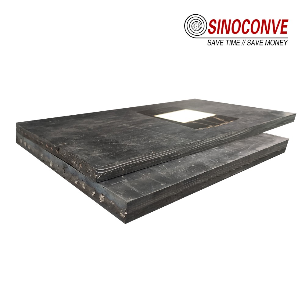
Two decisions do most of the work on a coastal unloader: how thick and how soft the cover is at the loading point, and what kind of carcass carries the tension. Everything else, the edge, the splice, the idler pattern, follows from those two.
Cover Thickness and Compound at the Impact Zone
On a receiving belt under a grab we start at 10 mm of top cover and go to 12 mm when the grab is large or the drop is over 15 m. Bottom cover stays at 4 to 6 mm because it does no work and only adds weight and bending stiffness. The compound matters as much as the thickness. A natural rubber blend at 55 to 60 Shore A deforms under a lump and spreads the load over a wider patch; the same cover at 68 Shore A resists cutting but transmits the strike straight into the cord.
We would rather supply 10 mm at 58 Shore A than 6 mm at 70. Tear strength above 60 N/mm and tensile strength in the 18 to 25 MPa range are the figures we look for, with abrasion loss under 150 cubic millimeters on a standard test drum. Those numbers describe a cover that gives a little and recovers, which is exactly what an impact zone needs.
Steel Cord, EP, and the Rip-Stop Layer
A fabric carcass in EP 630/4 or EP 800/4 handles most boom conveyors up to about 1,400 mm width. It is forgiving, it troughs well, it splices with a step pattern any crew can cut, and it tolerates a misaligned structure. Above that width, or where the take-up travel has to stay short, steel cord becomes the better answer: ST 1000 to ST 2000 gives very low elongation at working tension, so the boom does not need a long gravity take-up buried in the gantry.
Steel cord brings its own weakness. The wires are brass coated to bond to the rubber, and that coating is the first thing to suffer when water enters a cut or a splice. A rubber conveyor belt with a steel carcass is a superb belt on a dry inland duty and a liability on a wet coastal one if the edge is open.
The rip-stop layer is the third option and the one most often mis-sold. Transverse cords or a leno fabric laid between cover and carcass stop a longitudinal rip from running the length of the belt after a chute lip or a piece of angle iron gets caught. On a grab-fed receiving belt, that is worth paying for. It also stiffens the belt across its width, which costs troughability and adds a splice step, so it does not belong on every section of the machine.
| Carcass option for the boom conveyor | Where it performs best on this machine | Limits we tell buyers about before they order |
|---|---|---|
| High tensile EP fabric with four or five plies | Short boom flights with moderate tension and tight pulley centers | Thicker splice steps that can foul a tight chute lip |
| Brass coated steel cord with a closed edge | Long boom runs where low stretch keeps take-up travel small | Water reaching the wires corrodes the coating and kills adhesion |
| Steel cord with a transverse rip stop layer | Receiving belts under grab impact where a long rip is the risk | Stiffer across the width, so troughing needs a longer transition |
If the receiving belt and the boom belt differ in carcass, the splice at the transfer joins two belts of different stiffness and will always be the first to fail. Keep one carcass family across the machine, or put a real chute between them.
05Preventing Rollback and Spillage on Steep Boom Inclines: Chevron Patterns vs Sidewalls
A luffing boom on port conveyor steep transfer systems changes angle all day. At the top of the lift the incline may reach 22 degrees, and at that angle a smooth belt carrying lump coal will start to slide the load backwards, especially during acceleration or when the feed is uneven. The material does not stop at the tail pulley. It packs into the take-up area, rubs the return strand, and eventually buries the pulley.
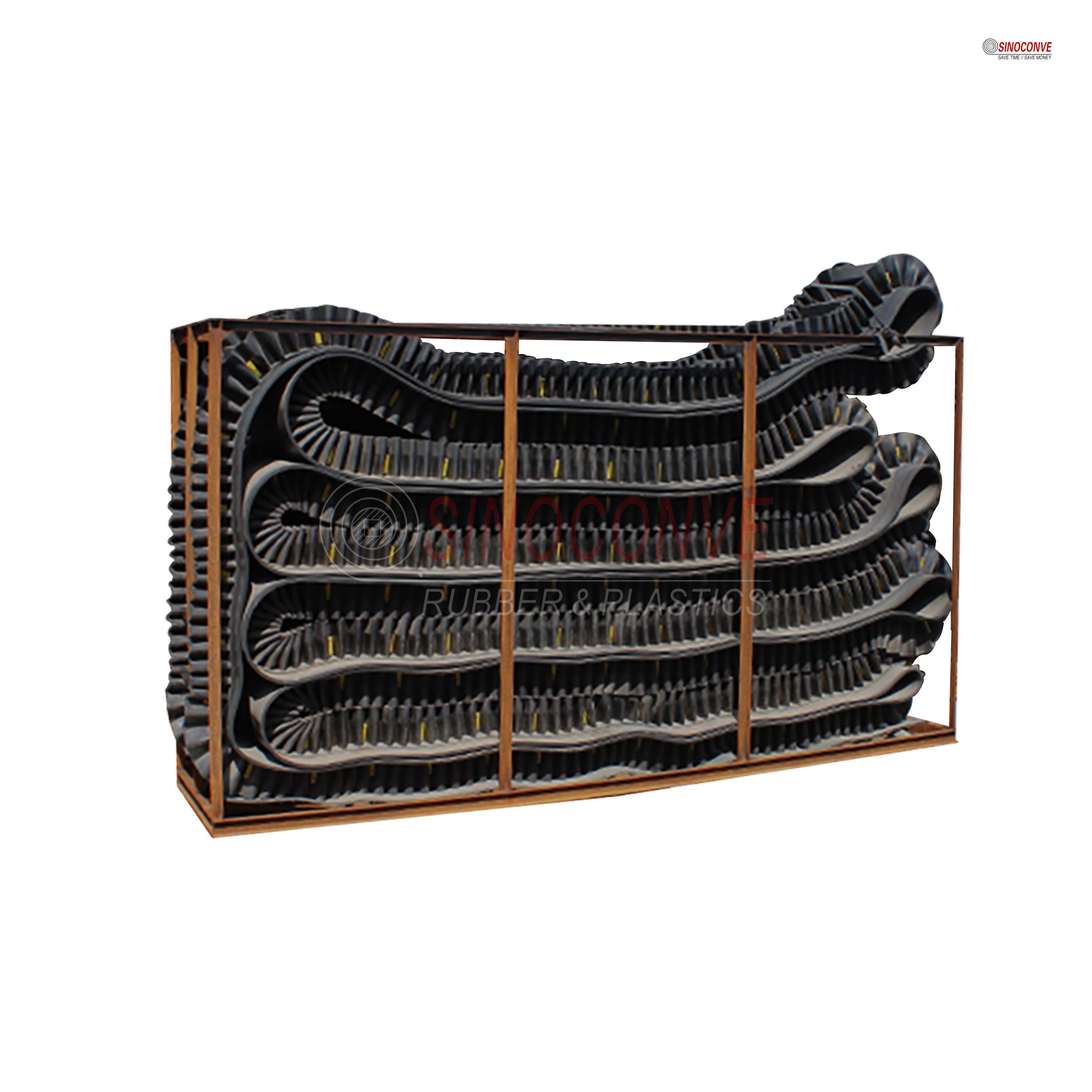
Chevron Profiles: Height, Pitch and the Discharge Problem
A chevron cover adds 6 to 20 mm of molded rib in a V or lance pattern, with pitch between 200 and 400 mm. On coal and coke it buys you roughly eight to ten degrees over a smooth belt, which is enough for most luffing booms. Above 25 degrees the benefit flattens out and the ribs start to work against you.
The cost appears at the discharge end. Ribs carry material around the head pulley and drop it into the chute a fraction later than a flat belt would, so the trajectory has to be recalculated rather than copied from the previous installation. Ribs also mean a larger pulley: the pulley diameter has to clear the cleat height with margin, or the belt will crack at the base of every rib within a season.
Two more details catch people. A chevron belt cannot be cleaned with a standard doctor blade, because the blade rides on the ribs and wears a groove into the cover, so plan on a rotating brush or a water spray instead. And the pattern must stop short of both edges, typically 50 to 100 mm of bare cover each side, so the skirt rubber at the loading point has something flat to seal against.
Corrugated Sidewalls Where the Angle Passes Thirty Degrees
When the geometry pushes past 30 degrees, or when the machine is a continuous unloader with a genuinely vertical lift, chevrons are no longer enough and a corrugated sidewall belt takes over. Sidewall heights from 40 to 120 mm with cross cleats at 200 to 400 mm pitch will hold material at 45 degrees and beyond, because the material is carried in a pocket rather than resting on a surface.
Sidewalls are a bigger commitment. The base belt is flat and often narrower for the same capacity, the pulleys need relief grooves or a special profile, and the belt cannot be run fast. Cleaning is awkward, and a damaged sidewall is not something a maintenance crew repairs at the berth. We generally recommend them for the fixed incline section of a continuous unloader, not for a luffing boom where the angle changes under load.
| Incline solution on a luffing boom | Steepest angle we would recommend for coal | The trade-off you accept at the discharge end |
|---|---|---|
| Smooth abrasion resistant cover with no pattern at all | Around sixteen to eighteen degrees before the load starts sliding | None at all, which is why it is still the first choice below the limit |
| Chevron or lance pattern molded into the top cover | Twenty five degrees, and twenty eight with a well controlled feed | Recalculated trajectory plus a brush instead of a scraper blade |
| Corrugated sidewall with cross cleats forming pockets | Forty five degrees and beyond on a fixed incline section | Relief grooved pulleys and a slow belt that is hard to clean |
Field note from our engineers: A terminal once blamed the chevron belt for a loaded boom that ran backwards after a power trip. The belt was innocent. Chevrons stop material sliding on the belt; they do nothing to stop the belt itself from reversing under the weight of a full incline. That is a backstop in the drive, and theirs had been rebuilt with the wrong torque setting. Check the drive before you change the belt.
06Seaside Corrosion Protection for Splices, Idler Frames and Pulleys
A belt on a coastal unloader supplied by an experienced port conveyor belt supplier is a small part of a corrosion problem that includes every frame, every bolt and every pulley face within reach of spray. The belt gets the attention because it is expensive, but it usually fails because something around it failed first.
The Splice Is the First Place Water Gets In
A hot vulcanized splice is a series of stepped joints, and every step is a potential wick. On a steel cord belt we cut steps of 250 to 400 mm depending on cord pitch, press at around 145 to 150 degrees Celsius for the full cure, and finish with a cover strip that overlaps the original cover by at least 50 mm on each side. The overlap is not cosmetic. It is the only barrier between salt water and the cord ends.
Done properly in a workshop, a steel cord splice reaches 85 to 90 percent of belt strength. Done on a berth in humid air with a damp carcass, it reaches less, and it will start to separate at the edges within a year. We press our splice samples in the same conveyor belt factory that makes the belt, and we would rather send a spliced and tested length than have a crew learn on your machine.
Two habits extend splice life at the coast. Seal the edges with a layer of tie gum before the final press, and mark the splice so inspectors can measure edge lift monthly. A 2 mm lift is a warning. A 6 mm lift means water has been in there for a while.
Frames, Idlers and Pulleys in Salt Air
Idler frames should be hot dip galvanized at 80 to 120 microns, not painted. Paint fails at every weld and every bolt head, and once it fails the steel underneath pits from the inside of the joint outward. Roller shells need a sealed bearing with a labyrinth path, because a bearing that breathes salt air on every thermal cycle will lose its grease in a season.
Watch the dissimilar metals. A galvanized frame with stainless fasteners becomes a small battery in wet conditions, and the galvanizing disappears around the bolt holes first. Nylon washers are cheap insurance. On the drive pulley, ceramic lagging holds grip far better than plain rubber when the surface is wet. Washdown with fresh water at the end of a shift does more for all of this than any coating.
The auxiliary drives are usually forgotten until they squeal. The hydraulic power pack fan, the washdown pump on the gantry and the compressor on the service deck are all small belt duties, and they sit in the same salt air as everything else. As a v-belt manufacturer we keep wrapped and cogged profiles for those drives in stock, and as a transmission belt manufacturer we supply the synchronous belts for the lubrication pump and the positioning drives on the boom. A seized fan belt can take an unloader out of service as effectively as a torn main belt, and it costs a fraction as much to prevent.
07Receiving Inspection and Commissioning Verification at the Berth: Terminal Stock Planning
A belt that arrives at a coastal terminal has crossed an ocean in a container, sat in a yard, and been lifted by a crane never designed for it. Damage in transit is common, and almost always at the edge or the roll end. Inspect before the roll goes up the gantry; once it is on the boom, every argument about who caused the damage gets harder.
What to Measure When the Belt Lands
We send a measurement sheet with every order, and as a conveyor belt supplier we expect the receiving engineer to use it. The checks are simple and need no laboratory. A cover gauge, a tape, a knife and an hour of daylight will catch nearly every defect that matters.
| Check performed when the belt arrives | How we measure it at the berth | The reject limit we would apply |
|---|---|---|
| Top cover thickness along the whole roll | Ultrasonic gauge at ten stations spaced along the roll | Any reading more than one millimeter below the ordered figure |
| Cord pitch and cord count at the cut end | Count and measure across the exposed end face | Pitch varying more than two millimeters between adjacent cords |
| Edge condition and the quality of the seal | Visual check plus a knife test at three random points | Open fabric or bare cord visible anywhere along the edge |
| Splice position and the length of each step | Tape measure each step against the approved splice drawing | Steps shorter than the drawing by more than twenty millimeters |
| Roll length and the squareness of both cut ends | Measure both edges and compare the two diagonals | More than fifty millimeters of difference between diagonals |
Commissioning is the second half of the same job. Run the belt empty for two hours and watch the splice pass the head pulley a hundred times before any cargo goes on it. Check that it sits centered through the full luffing range, not at one angle, because a belt that tracks at 15 degrees often wanders at 22. Then load in steps and watch motor current. A reading that climbs faster than the tonnage means the skirt rubber is pinching.
Spare belt storage deserves a paragraph of its own. A spare roll left on its side in the open will take a set across its width and will age on the exposed face. Store it on a pallet, under cover, off the ground, and rotate it once a year. The handling rules for a covered transfer building are much the same as those for belt handling inside warehouse and distribution operations, and a terminal that treats its spare roll like warehouse stock will not be surprised by it in three years.
If you are writing the enquiry for a new boom belt, send the machine duty sheet rather than the old belt dimensions. Grab size, drop height, belt width, speed, rated capacity, the full range of luffing angles, the cargo mix through the year, and what the washdown water actually is. We have been a conveyor belt manufacturer long enough to know that the last two change the answer more than the first four, and they never appear on a drawing.

08Frequently Asked Questions About Ship Unloader Conveyor Belts
How much drop can a ship unloader conveyor belt survive before the carcass is damaged?
More than most buyers expect, if the loading zone is built properly. We commonly supply 10 to 12 mm of top cover over a steel cord carcass under grabs that open 10 to 15 m above the belt, and those belts run three years or more. The limit is set by the support underneath, not by the rubber alone. Without cushion idlers or a dead bed of material, a 12 mm cover will fail nearly as fast as a 6 mm one.
Does salt mist really shorten belt life, or is that overstated?
It shortens the life of the interfaces, not the rubber itself. A cover compound sits in salt fog for years without losing tensile strength. What fails is the brass coating on a steel cord, the fabric at an open edge, and the bond inside a splice that has taken water in. That is why we insist on closed edges and sealed splices on any coastal machine.
Can a standard flat belt climb the 25 degree incline on our boom?
No. Above roughly 18 degrees with coal, the load starts sliding back during acceleration even when the surface is dry. A chevron pattern buys eight to ten degrees, which covers most luffing booms. If your geometry is steeper, the answer is a corrugated sidewall on the fixed incline section, not a steeper angle on the boom belt.
How long should a hot vulcanized splice last in a seaside terminal?
Three to five years when it is pressed dry, sealed at the edges and inspected monthly. Less than two when it is pressed in humid air with no edge seal, which is what we most often find on machines repaired at the berth. The splice is the cheapest thing to get right and the most expensive thing to get wrong.
Do we need a full spare belt on site, or is a repair kit enough?
A repair kit handles a puncture. It does not handle a 40 m longitudinal rip. Terminals that cannot afford to wait for a container should hold one boom length plus a section of receiving belt, stored on a pallet under cover and rotated once a year. That stock is less an inventory cost than an insurance policy on the berth window.
Is a continuous ship unloader belt different from a grab unloader belt?
Yes, in where the punishment sits. On a grab machine the receiving belt takes the impact and the boom runs comparatively clean. On a continuous unloader with a vertical lifting leg, the belt in that leg carries material in pockets, runs slowly, and needs sidewalls and cleats that a grab machine never uses. One specification for both machines is a false economy.
Related Products You May Need
- Steel cord belt for the boom run and the receiving point
- Chevron patterned cover for luffing booms above eighteen degrees
- Corrugated sidewall belt for vertical lift sections
- Cushion impact rollers to spread the grab discharge load
- EP fabric belt for the yard conveyor behind the gantry
Related Blog Posts
- What a port conveyor belt supplier should ask before quoting
- Steep transfers, spillage and bulk terminal belt selection
- Selecting a steel cord belt for heavy duty service
- Corrosion resistant rollers for coastal installations
- Stock planning for belts in mines, plants and ports
- Why splices fail and how to read the evidence