
Conveying solutions for mining are designed backwards from the tonnage, not forwards from a catalogue. A mining conveying system has to move a stated tonnes-per-hour figure from a working face, through a crusher and across transfer points, out to a stockpile or a long overland route. Where you draw the boundary and how the capacity check closes decide the cost of the project far more than the cover grade printed on the belt.
We are a conveyor belt manufacturer based in Ningbo, and our engineers have sized, supplied and commissioned conveying lines for hard-rock quarries, coal yards, iron ore operations and cement limestone pits. This page takes the design view. It covers the system boundary, route and transfer-point layout, a worked capacity and incline check, drive and tension behaviour, the component combination across a whole line, the environmental envelope, and a purchasing checklist a buyer can carry into a tender. If your need is field service rather than design, a companion article in this cluster is the better starting point, and section 07 explains the split.

01System Boundary: Where a Mining Conveying Design Starts and Stops
A mining conveying system begins at the point where material leaves the loading equipment and ends at the point where the next process takes ownership of it. That sounds trivial until a tender arrives in which the crusher discharge, the stockpile stacker and the overland flight are treated as three separate purchases with three separate drawings. The tonnage does not care about your purchase orders. If nobody owns the numbers between those three packages, the transfer chute will be built too small, the overland belt will be ordered 200 mm too narrow, and the stacker will arrive with a boom angle nobody can feed.
The four nodes every mine conveying line shares
Whatever the commodity, a mining conveying solution resolves into four nodes. First comes the extraction interface, a loader, a shovel, a feeder or a bunker discharge underground. Second is size reduction, where a primary or secondary crusher sets the top lump size and therefore the impact loading and the minimum belt width. Third are the transfer points, the towers and chutes where one flight hands material to the next. Fourth is the destination, whether that is a conical stockpile, a rail or truck loading station, a barge berth or a silo feeding a mill. Each node imposes a different demand on the rubber conveyor belt, the idlers and the structure, and the design job is to carry one consistent tonnage across all four without a hidden bottleneck.
In practice the destination node is the one most often underestimated. A stacker that must build a 12 m high cone, or a loader that must fill a 40 t truck in ninety seconds, generates surge peaks that can be 30 to 50 percent above the steady design rate. If those peaks are not written into the capacity calculation at the start, they reappear later as spillage, belt slip and stalled drives.
What sits outside the design boundary
Everything upstream of the face and downstream of the destination belongs to somebody else, and the boundary should be marked on the drawing rather than left to a meeting. Within the boundary we size the belt, the idler spacing, the drive, the take-up, the chutes and the safety devices, and we state the operating data that the whole package depends on: tonnage, density, lump size, moisture, temperature, hours per day and gradient. Outside the boundary sit civil works, the truck fleet, the crusher internals and the plant control philosophy. Mixing those into a belt enquiry produces a quotation nobody can compare, which is why the first page of any serious specification is a boundary statement and not a component list.
02Route Selection and Transfer Points Across a Mine Site
Route selection is a geometry problem before it is a belt problem. On a level site almost any line will work, and the choice narrows to civil cost and access. Add a vertical climb and the geometry starts to dictate the diameter of the drive pulley, the tension rating of the carcass and the number of driven pulleys, because a single flight covering 150 m of lift behaves very differently from two flights of 75 m each with a transfer tower in between.
Reading horizontal and vertical layout in one pass
We ask for a plan view and a profile on the same sheet, with chainage marked every 50 m. On that combined drawing it becomes obvious where a future second bench will cross the line, where a haul road has to pass under the belt, and where a vertical curve is too tight for the belt to stay seated. A industrial conveyor belt tolerates a concave transition only above a minimum radius, and that radius scales with tension, so a curve that looks harmless at the drawing stage can lift the belt off the idlers at full load. Standard practice is to keep curve radii generous and to place no idler closer than about 1.5 m to a pulley on the loaded run.
Counting transfer points and the real cost of drop height
Every transfer point costs structure, dust control, wear and maintenance, so the default is to keep the number low. The counter-argument is that fewer transfer points means longer flights, higher tensions and heavier drives. On a typical quarry line we see five to eight transfers between the primary crusher and the stockpile, and each one is a place where material free-falls, generates dust and loads the receiving belt at a localised point. Drop height matters more than most people assume. A 3 m free fall onto a 1,000 mm belt concentrates the whole stream onto a strip a few hundred millimetres wide, and that strip is where the cover fails first.
| Transfer point type | Where it is used on a mine site | Design points that decide whether it will last |
|---|---|---|
| Inline chute between two inclined flights | Most bench and ramp conveyors where the profile simply steps down a terrace. | Inlet hood, dead-bed stones, and a discharge angle that matches the receiving belt's direction of travel. |
| Tower with a 90 degree turn | Plant entries where the line has to change direction around a crusher house or a road crossing. | A vertical drop, a lined impact box, and enough headroom for the material to slow before it lands. |
| Crusher discharge spoon | Directly under a jaw or cone, where the stream is fast, hot and lumpy. | Impact idlers on close spacing, a steep spoon angle, and a belt that can take 150 mm and larger lumps. |
| Stacker or tripper feed | Stockpiling and blending, where the receiving point moves along the pile. | Surge allowance above nominal tonnage, and a chute that stays centred as the boom travels. |
Field note from our engineers: At an iron ore plant we surveyed a transfer tower where the drop was 4.2 m into a 1,200 mm belt. The customer had replaced the same 600 mm length of cover three times in eighteen months. We added a dead-bed shelf and a rubber-lined impact box that reduced the effective drop to about 0.9 m, and the replacement interval moved past three years. Nothing changed about the belt itself.
03Capacity and Incline Check: Closing the Numbers Before You Buy
Two calculations ruin more mining conveying projects than any hardware fault. The first is the capacity check, which links tonnage to belt width and speed. The second is the incline check, which links lift to belt length and decides whether one flight will do the job. Both can be closed on one sheet of paper, and both should be closed before a single quotation is requested.
Step one: turn tonnes per hour into belt speed and load area
Take a crushed granite stream at 1,500 t/h with a loose bulk density of 1.6 t/m³. The volumetric rate is 1,500 divided by 1.6, which is 937.5 m³/h, or 0.2604 m³/s. Choose a belt speed of 3.5 m/s, a common figure for a primary haulage flight on a mine site. The material cross-section the belt has to carry is then 0.2604 divided by 3.5, which comes to 0.0744 m². That number, usually expressed as 744 cm², is the single most useful figure in the whole design, because belt width tables are built around it. A buyer who never sees it is buying a width on somebody's intuition.
Speed itself is a trade. Raising the speed from 3.5 to 4.0 m/s cuts the required area to 0.0651 m² and can drop you into the next width class down, but it also raises wear at the loading point, increases the dust generated at every transfer, and shortens the life of skirts and rollers. On lumpy granite we would rather run a wider belt a little slower than a narrow belt at 4.5 m/s.
Step two: choose the width class from the load area
With the required area known, the width comes from a troughing table. For a three-roller 35 degree trough and a filling factor of 0.9, the effective load areas and the corresponding tonnages at 3.5 m/s and 1.6 t/m³ look like this.
| Belt width | Effective load area at 35 degrees | Tonnage at 3.5 m/s and 1.6 t/m3 | Where we see this width used |
|---|---|---|---|
| 800 mm | About 0.055 m2 | Roughly 1,109 t/h | Secondary and tertiary circuits, screen feed and clean product lines. |
| 1,000 mm | About 0.086 m2 | Roughly 1,734 t/h | Common primary discharge and stacker feed where the stream is steady. |
| 1,200 mm | About 0.121 m2 | Roughly 2,439 t/h | Main haulage from pit or underground where surge peaks have to be absorbed. |
| 1,400 mm | About 0.161 m2 | Roughly 3,246 t/h | High-capacity trunk lines and long overland flights feeding a plant or port. |
Our 1,500 t/h stream needs 0.0744 m², so a 1,000 mm belt passes the steady-state check with about 15 percent to spare. Then the surge question arrives. If the crusher discharge spikes 30 percent above nominal, the demand becomes 1,950 t/h and the required area 0.0967 m², which no longer fits a 1,000 mm belt. The honest answer to a 1,500 t/h enquiry with a peaky feed is a 1,200 mm belt, and that conclusion is worth far more than a few percent off the belt price. A reputable conveyor belt supplier will ask for the surge figure before quoting a width.
Step three: trade maximum incline against climb length
Now the vertical problem. Suppose a mine needs 150 m of lift and has 600 m of horizontal distance available. The route angle is the arctangent of 150 over 600, which is 14.0 degrees, and the belt length along the slope is 600 divided by the cosine of 14 degrees, or 618 m before terminations. Crushed rock on a smooth rubber cover holds well up to roughly 16 to 18 degrees, so a single 14 degree flight is a comfortable design, and the extra length over the horizontal run is only about 3 percent.
Change one number and the whole answer changes. If buildings force the same 150 m of lift into 300 m of ground, the angle becomes 26.6 degrees, which is beyond what a smooth cover can hold. Three options follow, and each has a price. You can split the lift into two flights with a transfer tower, which adds a structure but keeps the angle safe. You can move to a chevron or cleated belt, which holds 22 to 25 degrees with shallow ribs and up to about 30 degrees with deep 16 mm ribs because the ribs carry material on the incline instead of relying on friction alone. Or you can re-route entirely. Deep ribs cost more per metre and complicate cleaning, so on a long mine flight we usually prefer two smooth-belt stages.
Incline also feeds straight back into power. At 14 degrees the slope component of the load is the sine of the angle, 0.242, so close to a quarter of the material weight per metre is being lifted rather than merely pushed. That is why the drive calculation in the next section cannot be separated from the route geometry.
04Drive, Tension and Starting Behaviour
Once the geometry is fixed, the drive is sized from the belt tension, and the tension is sized from the resistance. For the 618 m incline carrying 1,500 t/h, the power needed simply to raise the material is 1,500,000 kg per hour divided by 3,600 and multiplied by 9.81 m/s² and 150 m, which is about 613 kW. Add belt friction, idler rotation, drive efficiency and the empty-belt component over 618 m, and installed power lands close to 1,000 kW. That is why a line of this size is normally quoted with three driven pulleys rather than one.
Multi-drive arrangement and load sharing
Spreading the power over three motors of about 400 kW each keeps individual gearbox and pulley sizes manageable and gives useful redundancy if one unit drops out. The catch is load sharing. Motors that are not matched in speed droop will fight each other, and the strongest one carries more than its share until it trips. We specify motors whose speed regulation keeps the spread inside about 2 percent, and on larger drives we prefer a variable-frequency master-slave arrangement so torque is allocated by the controller rather than by luck. Where a mine keeps V-belt drives on the crusher and screen motors, those auxiliary drives are a separate selection problem, and a transmission belt manufacturer should match the pulley grooves to the duty.
Soft start, braking and backstops
Starting a loaded 618 m incline is the hardest moment the drive will ever see. A direct-on-line start can pull three to four times full-load torque for several seconds, which stretches the belt and hammers the splices. Fluid couplings or a controlled VFD ramp, normally over 20 to 40 seconds for a long incline, keep starting tension inside the splice rating and let the take-up follow the stretch instead of fighting it. Direction of failure matters just as much: any incline steep enough to let a loaded belt run backwards needs a backstop, and long regenerative sections need a brake that can hold at standstill and release gradually. Reverse-running detection should be wired to trip the drive, not just to sound an alarm.
Tension is finished off by the take-up. Gravity towers give constant tension and are the choice on long overland flights, but they need a shaft or a tower with the full travel available. Screw or winch take-ups are cheaper and suit shorter lines, at the cost of needing adjustment as the belt creeps. Whichever type you choose, state the required travel in the specification. A belt that needs 2.5 to 3.0 m of travel with only 2.0 m available will never carry full tonnage. The tension budget, not the belt catalogue, decides how much take-up travel you must build into the structure.
05Component Combination Matrix: Which Part Serves Which Segment
A mine conveying line is not one belt repeated in six places. Each segment sees a different load, a different speed and a different failure mode, and the component combination should be written segment by segment. This is where a design view separates itself from a shopping list: the cheapest way to fail a project is to order one belt type, one idler type and one cleaning arrangement for the entire line, then wonder why the discharge end wears out twice as fast as the incline.
How to read the matrix by route segment
Read each row as a contract with the material. At the loading point the stream is fast and lumpy, so impact idlers on tight spacing and a thicker top cover carry the load. On the long trunk flight the priorities reverse: low rolling resistance and a stable track matter more than impact strength, because idler drag over several kilometres adds up to real power. Around transfer towers the enemy is spillage and dust, so sealing and skirt geometry lead. The matrix below is the one we use when we write a specification for a mixed line, and the columns map onto how a purchase order is usually split.
| Route segment | Belt carcass and cover | Idlers and spacing | Cleaning, enclosure and dust | Safety and monitoring |
|---|---|---|---|---|
| Loader and crusher mouth | High-abrasion top cover over a carcass that resists cut and gouge. | Rubber-disc impact idlers at 300 to 400 mm, then normal troughs. | Skirt rubber, a stone box in the chute, and a spray bar. | Pull-cord and alignment switches on both sides of the loading zone. |
| Primary haulage, fairly level | EP fabric carcass, moving to steel cord past about a kilometre. | Three-roller troughs at 1.0 to 1.2 m, self-aligning set every 20 frames. | Primary and secondary scrapers at the head, a cleaner on the return side. | Speed and slip sensing at the head pulley, belt-tear loop on long flights. |
| Incline and steep sections | Chevron ribs rather than a smooth cover once the feed can be wet. | Closer trough pitch to centre the load, good return rollers against sag. | V-plough to clear material that rolls back under the belt. | Backstop on the drive, reverse-motion detection wired to trip. |
| Long overland trunk | Steel cord for the tension, low rolling resistance covers to cut power. | Low-drag sealed idlers at 1.2 to 1.5 m pitch, catenary kept stable. | Full enclosure or hood over the loaded run against wind and rain. | Distributed pull-cords, a belt weigher, and drive temperature sensors. |
| Transfer tower, stockpile and loader | The belt passes through; liners and dead beds take the wear instead. | Impact and troughing idlers stacked under the impact zone, spiral sets near the pile. | The main dust source, so extraction and enclosure are settled here first. | Emergency stop, blocked-chute probe, and reachable access platforms. |
Carcass choice: steel cord or EP fabric
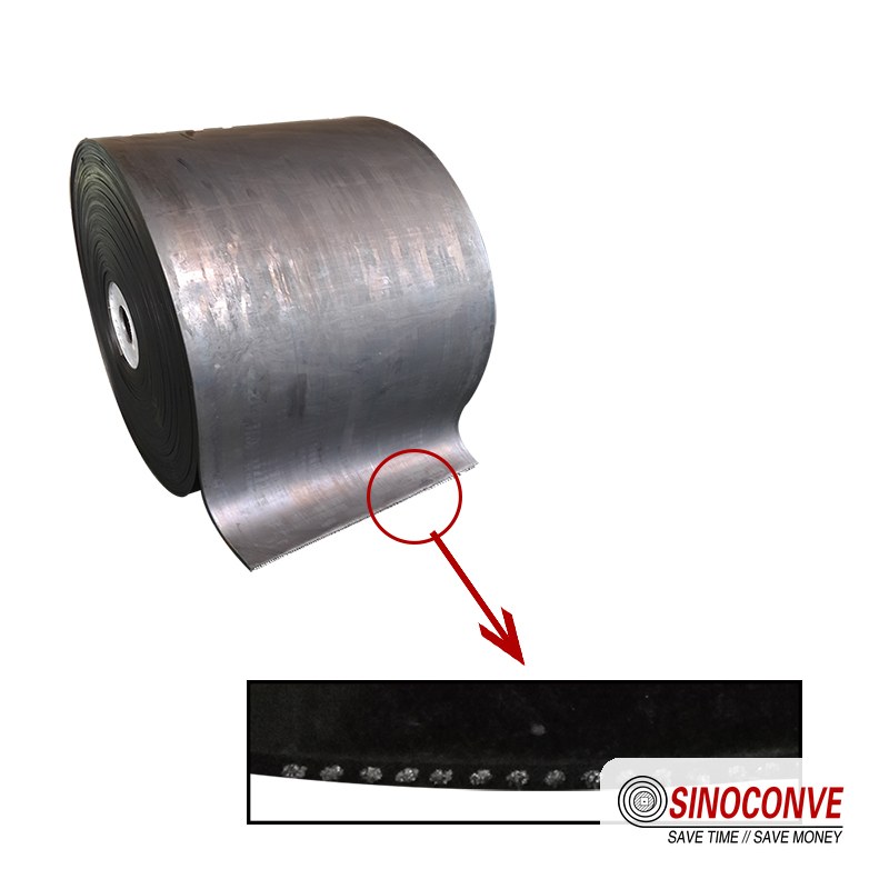
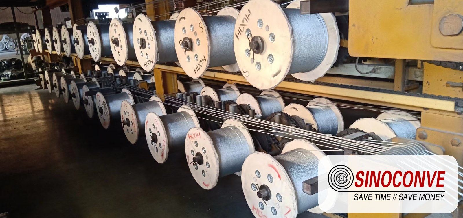
The matrix keeps forcing one question back to the top of the line: which carcass. EP fabric does the majority of mine work, from an 800 mm plant belt up to a 1,400 mm trunk flight, and it splices quickly with a hot vulcanised finger joint a trained crew can complete in a shift. Steel cord takes over where tension climbs, typically on long overland flights beyond about 1,000 m or on very high-lift inclines, because a single cord layer carries far more than a stack of fabric plies and stretches less under load, at the price of a more careful splice and a larger pulley. We size the carcass from the calculated maximum tension with a design factor typically between 8 and 10 on fabric and around 6.7 on steel cord.
Cover grade follows the segment, not the carcass. A DIN 53516 abrasion figure of roughly 90 mm³ suits clean product, 150 mm³ covers most quarry rock, and 250 mm³ or better belongs at a crusher discharge where the lumps and the drop are both severe. When a mine group buys for several sites at once and issues the enquiry as wholesale conveyor belts from a central office, the same construction has to be available across every width and grade in the schedule, which is the kind of range a belt factory with its own mixing and curing lines can hold. The crusher drives beside these belts run on V-belts, and a V-belt manufacturer should match profile, groove and tension to the driven machine.
06Environment, Dust and Climate Effects on a Mining Conveying Design
The environment is not a finishing touch on a mine conveying design; it rewrites parts of it. Dust, cold, altitude and wet-season moisture each change what the belt, the idlers and the electrical package have to tolerate, and a system designed on a mild dry day will fail in the first monsoon or the first night at minus 30 degrees Celsius.
Where dust becomes a real hazard, not just a housekeeping problem
Fine coal, sulphur, metal concentrate and many other mine products can form an explosive dust cloud, and a conveyor is one of the few places in a plant where that cloud is generated continuously. Ignition at a hot bearing is the first risk, which is why flame-resistant belting meeting a recognised fire test is standard for coal and concentrate, and why bearing temperature monitoring earns its cost there. Accumulation is the second, because a 1 mm layer of fine combustible dust across a transfer tower floor is enough to propagate a secondary explosion once something lifts it. Enclosure, extraction and a cleaning schedule that removes that layer are part of the design, not a housekeeping afterthought.
Anti-static and flame-resistant constructions are worth specifying together on fuel-handling lines, and the water used for dust suppression carries a cost of its own, because a belt that stays wet has to resist hydrolysis while the structure drains. A chevron belt selected through a conveyor belt distributor for a wet incline should be checked for rib adhesion, since the ribs are the first place a wet-facing bond fails.
Cold attacks different parts. At minus 20 degrees Celsius and below, standard rubber stiffens, troughing resistance rises and starting torque climbs with it. Low-temperature compounds stay flexible at a higher price, and the cold hardens the grease in idler bearings, which turns a well-sized drive into a marginal one. Altitude compounds this by thinning the air available for motor cooling, so a drive rated at sea level may need derating above roughly 1,000 m. A site that is both high and cold feels the two effects in one calculation.
| Environmental factor | What it changes in the design | How we usually answer it |
|---|---|---|
| Combustible fine dust | Turns every transfer tower into a potential ignition and accumulation zone, and rules out ordinary belting on coal and concentrate. | Flame-resistant and anti-static belts, enclosed transfers with extraction, and bearing temperature monitoring on drives. |
| Extreme cold | Stiffens the belt, raises troughing resistance and starting torque, and hardens bearing grease. | Low-temperature compounds, larger installed power, and a longer soft-start ramp on the drive. |
| High altitude | Reduces air density, so motors and gearboxes cool less effectively at the same load. | Derate the motors above about 1,000 m and confirm the gearbox thermal rating for the site. |
| Wet season and moisture | Raises bulk density, promotes chute adhesion, and can push a marginal incline past its holding angle. | Steeper chutes, drainage on the structure, and ribbed belting on the one flight nearest the limit. |
| Wind across an open pile | Carries fines off the stacker and off the loaded belt where enclosure is incomplete. | Wind fences around the pile and a hood over the exposed loaded run on the overland section. |
07How This Design View Differs from Our Service Article and the Existing Systems Page
Three pages on this site touch mining conveying, and buyers keep asking which one to read first. The honest answer is that they answer three different questions, and picking the wrong one wastes a week. We keep them deliberately separate so that a design decision is never confused with a contractual one.
Which page answers which question
This page is the design view. It assumes a new or rebuilt line and works the numbers: system boundary, route and transfer-point layout, the capacity and incline check, drive and tension sizing, the component combination across each segment, and a purchasing checklist. The companion article "Mining and Quarrying Conveyor Services" takes the service view instead, covering the service menu a mine actually buys, survey and installation work, hot-splicing and roller change-outs, contract terms and the cost of downtime. If your line already exists and only needs maintaining, repairing or re-splicing, read that article. Deciding belt width, speed and installed power from scratch is a design task, and tendering it as a service job is how a project ends up with a correct belt on a structure no crane can reach.
A third, earlier page covers quarry conveyor systems in a general way, describing how a quarry-class line is organised from face to stockpile. That page is the right overview for a small or mid-size aggregate operation, but it stops short of the mine-grade arithmetic: long overland flights, multi-drive tension budgets, dust explosion risk and high-altitude cold. Where this article goes deeper, that page stays general, and we link to it rather than repeat it. Belt selection detail for crusher and aggregate plants also lives on its own page, so we do not re-run ply and cover tables here.
For the manufacturer behind all of it, our conveyor belt factory and service organisation are described in full, and the dedicated mining and quarrying section lists the product families we supply into this market. Readers who want the field-conditions background first can start with our heavy-duty rubber conveyor belt discussion of mining duty, or the crusher and aggregate belt selection page that covers the belt choice following on from the design described here.
08Purchasing Checklist and Acceptance Criteria for a Mining Conveying Solution
By the time a mine conveying solution reaches the purchasing stage, most of the risk has already been created or avoided on paper. The job of the buyer is therefore not to compare unit prices but to compare the technical package behind them. Two quotations for the same "1,200 mm steel cord belt" can differ by more than the belt itself, because one of them has done the tension calculation and the other has copied last year's order.
The document package to request from every bidder
Ask for the same eight documents from every supplier, and price the answers rather than the promise. A supplier who cannot produce a tension sheet is not offering a design, only a belt.
| Document to request | Why it decides the price later | Acceptance criterion to write into the order |
|---|---|---|
| Route drawing with plan and profile on one sheet | Fixes chainage, lift and transfer positions, and exposes any curve too tight for the belt before steel is cut. | Signed drawing at 1:500 with chainage every 50 m and all vertical curves dimensioned to a stated radius. |
| Capacity and tension calculation | Shows the tonnage, the load area, the width class and the maximum tension the splice must carry. | Both steady and surge tonnage stated, and a tension figure traceable to the stated density and speed. |
| Belt datasheet by width and grade | Confirms the cover grade, abrasion figure and ply or cord count that the duty actually requires. | Cover abrasion stated to DIN 53516 and tensile class to DIN 22102, with a test certificate on request. |
| Idler and pulley schedule | Decides bearing life, drag and the pulley diameter that the carcass is allowed to bend around. | Seal type, bearing size, spacing and pulley diameter listed per segment, with impact idlers at the load zone. |
| Drive and starting study | Determines installed power, motor matching and whether the starting torque will damage the splice. | Stated starting ramp time, load-sharing tolerance and backstop or brake provision for the incline. |
| Splice procedure and test evidence | The splice is usually the weakest point on the whole line and the cheapest thing to get wrong. | Written step and cure procedure, plus a sample test or a documented field procedure for the joint method. |
| Cleaning and dust control schedule | Carryback control decides idler life, spillage labour and how often the tower floor has to be cleared. | Scraper type and position per head and return side, with spray or enclosure matched to the material. |
| Safety device and switch schedule | A stop that cannot be reached in time is worth nothing, and a missing trip can cost a person. | Pull-cords, alignment switches, speed and slip sensors and reverse-motion trips listed per flight. |
Acceptance criteria that belong in the order, not in a meeting
Verification at handover should be measurable. Insist on a no-load run long enough to prove tracking and seat the belt on every pulley, then a full-load run at the design tonnage with a measured power draw inside the calculated figure. Scraper performance is easy to check by looking at the return strand for carryback after the loaded run; leftover material under the head pulley means the cleaning arrangement is not finished. Where a splice was made on site, ask for the cure temperature and time to be logged, because that single record tells a future crew how the joint was built. We publish a splicing buyer's checklist covering the twelve points worth verifying around joints, and it maps onto this stage of a design project.
Two criteria are usually forgotten and both are expensive. The first is a running record of belt alignment after the first 500 hours, when a new belt has taken its final stretch and the take-up has moved. The second is a documented turnover of the design data itself: the tension sheet, the belt datasheet and the drive settings, handed over as a package. Without that package the next engineer has to reverse-engineer the line from what is standing on the ground.
09Common Design Errors in Mining Conveying Projects
We review a lot of tenders and a lot of as-built drawings, and the same handful of mistakes keeps appearing. None of them is exotic. All of them are cheap to fix at the design stage and expensive to fix on site.
The mistakes we correct most often
The most common is a surge figure that never made it into the capacity calculation. The line is sized for the average tonnage, the crusher discharge peaks above it, and the belt sits at 110 percent of its load area several times an hour. Directly linked to that is a transfer drop height nobody measured, which turns the loading zone into the fastest wearing part of the line and keeps a crew busy replacing cover. A third is a take-up designed from the catalogue belt length rather than the tension budget, leaving too little travel for a belt that stretches as it works.
On the incline side we often find a single flight carrying an angle that would be fine dry and fails wet, with no allowance for the moisture that the wet season brings. We also see multi-drive installations with unmatched motors that fight each other until one trips, and inclines with no backstop because the original designer assumed the drive would always be energised. None of these needs a new belt. They need the calculation done properly before the order is placed, and that is the whole point of keeping the design view separate from the service view.
10Long Flights, Stockyards and Loading Interfaces
A mine conveying solution that stops at the plant gate is only half designed. The two interfaces that decide whether the whole line earns its keep are the long flight to the stockyard or port, and the loading station at the end of it, because both are places where a small design error repeats thousands of times a day.
Designing the overland trunk flight and its interfaces
Once a flight runs beyond about a kilometre, steel cord becomes the practical choice because the tension no longer fits a fabric carcass comfortably, and the steel cord conveyor belt range is built for exactly this duty. Two things then dominate the design. The first is rolling resistance, because over several kilometres idler drag is a permanent cost that never shows up in the purchase price; low-drag sealed idlers and a sensible pitch are worth real money per year, and the principles in our roller types, materials and load ratings guide apply directly. The second is exposure, because a trunk flight crossing open country meets wind and rain that a covered plant line never sees, so the loaded run needs a hood or enclosure and the structure needs drainage.
At the far end the material usually goes one of three ways: to a conical stockpile built by a stacker, to a reclaim tunnel feeding a second line, or to a rail or port loading station fed at the rate a ship or train sets. Each adds a surge behaviour of its own. A stacker builds a pile in layers and starts and stops, and a reclaim tunnel draws unevenly and can feed lumps that were never in the size range. A line feeding a port should be checked against the loading window, not the average day, and the port bulk material handling picture is close enough to a mine stockyard that the same rules apply. Belt selection for a berth favours stronger covers, since salt and wet fines are unforgiving.
Field note from our engineers: On a copper mine we were asked to price an 1,800 m overland flight. The original enquiry used a single drive at the head. Moving two motors to the tail pulley and keeping one at the head cut the maximum belt tension by roughly a third, which let the customer stay with a lighter and cheaper carcass and a smaller take-up tower. The routing never changed. Only the drive position did.
11Underground to Surface: The Transition That Decides the Rest
Where a mine works underground, the hardest part of the conveying design is rarely the flat drift. It is the transition where material comes up a steep incline from a bunker or a shaft loading point into the surface plant, because that single section has to handle the highest angle, the dampest feed and the tightest space on the whole route.
Steep haulage, damp feed and confined space
Underground incline haulage usually means a ribbed belt, because a smooth cover at 20 degrees and above with a damp, fine feed is a continuous gamble. The ribs hold the material, but they also trap it, which is why the return side of an underground incline needs a proper V-plough and a regular inspection of the return rollers; we cover the carryback side of this in our return side belt cleaning notes. Space underground is the second constraint.Headroom for an impact box is scarce, so the chute geometry is compressed and the material lands faster than on a surface line, which pushes the whole loading zone towards heavier impact protection such as the arrangements described in our impact rollers at loading zones article.
The surface end of the transition is where the design usually finishes. Material arrives wet, so the receiving chute needs a steeper slope than the dry-product rule of thumb, and it often carries more fines than the surface plant expected, which changes the dust load at the first transfer. Ventilation air moving up the drift also carries dust with it, so the first surface transfer is a natural place to put extraction. Get this transition wrong and every downstream flight inherits the problem, which is why we treat it as a designed section rather than a leftover.

12Frequently Asked Questions About Mining Conveying Design
How do I size a mining conveyor from a tonnage figure?
Divide the hourly tonnage by the bulk density, then by the belt speed, to get the required load area. Match that area to a troughing table for your trough angle and pick the width. A 1,500 t/h granite stream at 1.6 t/m³ and 3.5 m/s needs 0.0744 m².
What incline can a rubber conveyor belt actually hold?
Dry crushed rock on a smooth cover holds roughly 16 to 18 degrees, and wet or clayey material drops that to about 12 to 14 degrees. Shallow chevron ribs push the limit to 22 to 25 degrees, and deep 16 mm ribs reach about 30 degrees, because the ribs carry the load instead of relying on friction alone. Above that you need sidewall or pocket belting, which is a different design at a different cost. If your route forces more than 16 degrees with smooth belting and the feed can arrive wet, split the lift into two flights rather than accept a line that only works in the dry season.
Steel cord or EP fabric for a mine trunk line?
It comes down to tension. EP fabric covers most work up to a flight of about 1,000 m and splices quickly with a hot vulcanised finger joint. Steel cord takes over beyond that, or on very high lift, because a single cord layer carries far more and stretches less under load.
How many transfer points should a mine line have?
As few as the geometry and the tensions allow. Each transfer adds structure, dust and maintenance, but removing one lengthens a flight and raises tension. On a quarry line we see five to eight transfers between crusher and stockpile.
How do I design a conveyor against dust explosion risk?
Start from the material. Fine coal, sulphur and metal concentrate can form an explosive cloud, so specify flame-resistant and anti-static belting for those duties, monitor bearing temperatures at the drives, and enclose the transfer points with extraction. Then deal with accumulation, because a thin layer of combustible dust on a tower floor is what turns a small ignition into a serious event. A cleaning schedule is part of that design.
Can a conveying solution be quoted from tonnage alone?
No. Tonnage without density, lump size, moisture, temperature, gradient and surge cannot be checked, so two bidders are not pricing the same thing. A serious quotation comes back with a tension calculation that traces to the data you supplied.
How much take-up travel should I allow?
Enough for the belt to stretch under full tension across the whole temperature range and still hold correct tension. Long inclines and cold sites need more travel than short flat lines, and a long flight commonly needs 2.5 to 3.0 m. If the structure only offers 2.0 m, the belt will never reach full tonnage.
Why does a conveyor slip in the wet season when it ran fine dry?
Moisture raises the effective density, makes material stick in chutes, and reduces the friction holding a load on an incline. A flight at 15 degrees can hold perfectly dry and spill steadily once the feed is saturated.
What should I verify before accepting a new mine conveying line?
Run it no-load long enough to prove tracking, then at full design tonnage, and record the power draw against the calculation. Check the return strand for carryback after the loaded run and confirm the belt sits inside the trough without touching the side guides. Collect the logged splice cure temperature and time, and file the design data package with the order.
Conveying solutions for mining succeed or fail on the drawing board, long before a belt is spliced. Close the boundary, fix the tonnage and surge, check the incline against the geometry, size the drive from the tension, and match each component to its segment. Do that and the hardware behaves; skip it and the same mistakes reappear at every transfer.
Related Products You May Need
- Steel cord conveyor belt for long, high-tension overland and incline flights.
- Rubber conveyor belt in the abrasion, heat and flame grades a mine duty calls for.
- EP fabric conveyor belt for primary haulage and plant circuits up to about a kilometre.
- Conveyor rollers and idlers including impact, spiral and self-aligning types for loading zones.
- Chevron and cleated belt where the route forces material up a steep incline.
- Full product catalog covering belts, rollers and drive products for mining operations.
Related Blog Posts
- Heavy-duty belts in mining — what the working conditions do to cover and carcass over a service life.
- Abrasion-resistant belts for quarry and aggregate — how the wear actually arrives.
- Impact rollers at loading zones — protecting the belt exactly where the material lands.
- Steel cord belt durability and efficiency — when the cord carcass earns its price on a bulk line.
- Roller types and load ratings — matching shell, seal and bearing to the duty.
- Cleaning methods and schedules — carryback control when a scraper on its own is not enough.
- Dust-resistant belt supply — how fine material changes belt and roller choice on a mine site.
- Belt tracking field guide — the checks that come before anyone touches a take-up frame.
- Cover grades explained — reading the abrasion numbers against real rock duty.
- Spray cleaning on dusty lines — keeping fines out of the air at the transfer points.