
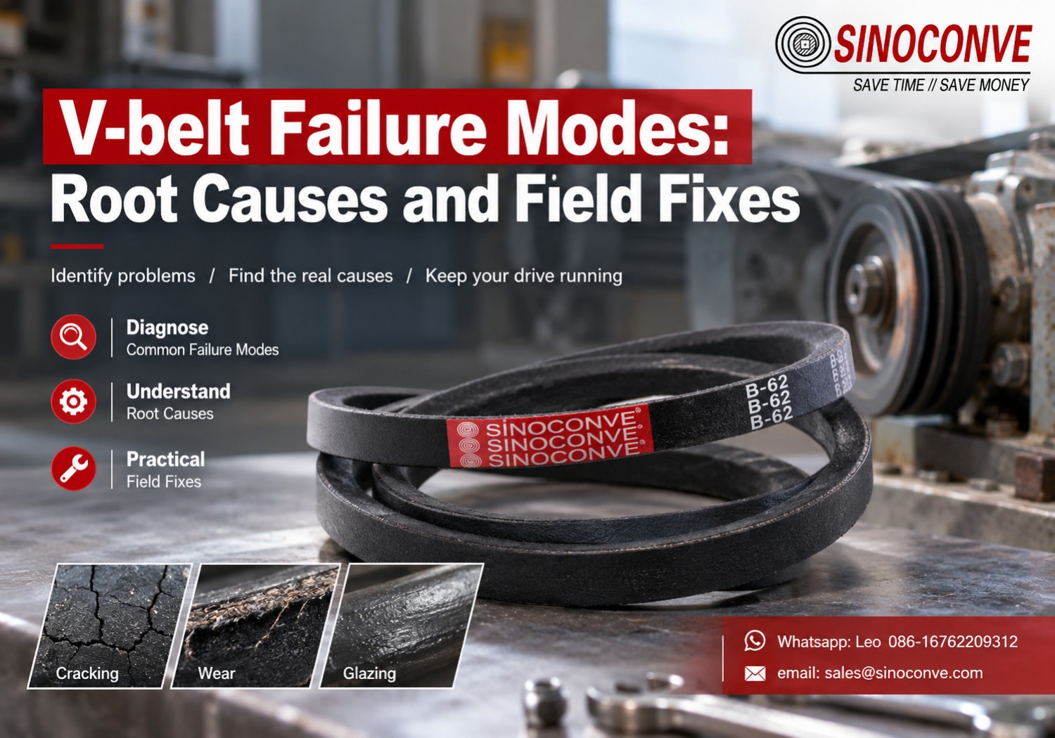
V-belt Failure Modes: Root Causes and Field Fixes
A failed V-belt is evidence, not a verdict. Each one carries a record of every hard start, every slipping load, every drop of oil, and every groove it spent its working life wedged inside. Read that record carefully and you fix the drive once. Read it wrong and you keep buying belts.
We are a transmission belt manufacturer in Ningbo, and failed belts reach our bench most weeks from mines, quarries, ready-mix plants and ports. The belts differ in size and brand. The stories behind them rarely do.
What follows is a diagnosis guide, not a maintenance schedule. Nine failure modes, the measurements that separate one from another, and the repairs that hold. For the installation side of the subject, our engineers already wrote a separate piece on choosing and maintaining a V-belt drive, and we will not repeat it here.

01Start With the Drive, Not the Belt
Why the Belt Is Usually the Last Component That Actually Fails
In our repair files, roughly one belt in three is genuinely the guilty component. The other two are messengers. A jackshaft bearing with 0.4 mm of radial play lets a driven pulley walk out of plane under load, and the belt reports that fault at its top cover long before anyone notices the bearing. The same is true of a motor sitting on slide rails that have slipped 3 mm, or a sheave whose groove has opened by half a millimetre after years of cement dust.
Replacing the belt buys a shift or two. Then the new belt dies in the same place. The plant tries another brand, then a heavier section, then a banded set. Three months later there are four pallets of the wrong answer in the store.
Bearings, alignment, groove geometry and tension. Those are the four variables we check before we say a single word about belt quality, and two of them are measurable with a straightedge and a vernier.
The Chain We Use: Symptom, Measurement, Root Cause, Fix
Every mode below follows the same order. What does the operator see? What can we measure in ten minutes with a straightedge, a groove gauge and a chalk mark on the floor? What does the belt show on the cross section? Which single root cause explains all three answers?
Two rules keep this honest. Measure before you theorise, always. And when two root causes both fit the evidence, run the cheaper test first — groove width before gearbox internals, tension before bearings. The arithmetic behind the numbers used here is set out in our drive engineering calculations guide.
Hours Are the First Filter, Condition Is the Verdict
Running hours split wear-out from abuse faster than anything else. A wrapped classical belt on a clean, aligned drive is commonly quoted at 10,000 to 25,000 running hours. Put the same belt in a crusher house with 42 °C air and airborne dust and 8,000 hours is a good outcome. Lose it in 300 hours and you are not looking at a belt problem. You are looking at a driven machine fighting its own drive.
Condition decides the rest. A belt with 20,000 hours and clean sidewalls may still be serviceable. A belt with 600 hours and a hard, shiny, glazed flank is finished, and the reason is sitting in the groove, not in the compound.
02The Symptom Map: Where the Damage Sits
Nine modes, and most of them leave their signature in a different place. That is the whole trick of diagnosis. A belt tells you where it hurt long before it tells you why.
Symptom-to-Mode Map
Read this table as a filter, not a verdict. It takes nine candidates down to two in about a minute.
| What you see | Most likely mode | First measurement | Hours we usually see |
|---|---|---|---|
| Evenly spaced cracks across the bottom face or cog roots | Bending fatigue | Small pulley datum diameter against belt height | 400–2,000 |
| Top cover lifting, fabric frayed along one edge | Heat, oil or misalignment | Straightedge across both pulley faces, then gearbox case temperature | 800–5,000 |
| Clean transverse break with almost no fraying | Overload or jam | Driven machine for blockage; key and coupling condition | Often under 100 |
| Hard, glossy flanks and a burnt smell | Slip from low tension or oil | Mid-span deflection, then a wipe test inside the groove | 200–3,000 |
| Belts sitting deep in the groove, take-up at end of travel | Elongation beyond limit | Datum length against the original, plus remaining slide travel | 2,000–10,000 |
| Sidewalls polished from top to bottom, groove floor shiny | Groove wear and mismatch | Groove gauge or a vernier across the groove at three points | 1,500–8,000 |
| One belt broken, the rest of the set still unbranded and fine | Matched-set length spread | Every belt of the set measured under the same tension | Any |
Those hour bands assume a four-pole motor, a centre distance of at least twice the large pulley diameter, and ambient air below 40 °C. Move any one of them and the numbers shift. They are a sanity check, not a warranty. The same geometry governs drives bolted to an industrial conveyor belt frame in the same building, which is why one plant often has the same failure repeated on three different drives.
How to Read the Cross Section Before You Clean It
Photograph the belt where it failed, in place, before anyone wipes it. Wet the break with a rag and the oil film becomes obvious; rub it dry and you have destroyed the best evidence you had. Then cut a 100 mm section from both sides of the break and lay the two halves side by side on the bench. Cracks that run across the bottom face and stop at the cord line point one way. Cracks that spread up through the sidewall and lift the cover point elsewhere entirely.
If the profile stamp on the back has worn off, measure the top width with a vernier and match it against a standard chart. A quick V-belt size chart check on top width alone identifies the section in most cases, and our colleagues set the profiles out properly in the profiles and sizes buying guide.
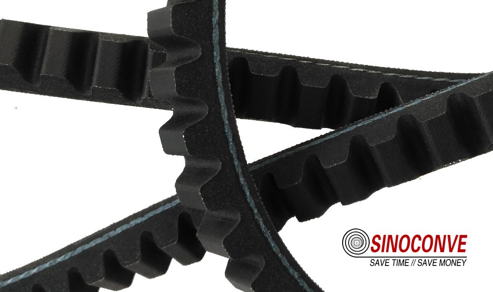
Cracks across the bottom face, no fraying. That geometry points to a pulley too small for the section.
03Mode 1: Bottom Cracking and Cog Root Splitting
This is the failure we see most often, and the one most often misread as bad rubber. Every revolution, the belt is forced to bend around the small pulley and then straighten again. On a 90 mm pulley spinning at 1,450 rpm, that is roughly 24 flex cycles per second, 86,000 an hour, two million in a day. The bottom face and the cord line take that fatigue first.
What the Crack Pattern Tells You
Bending fatigue is recognisable in about five seconds. The cracks are evenly spaced, they run across the bottom face or open at the cog roots, and they stop short of the top cover. The spacing matches the pulley circumference divided by the number of cogs, which is why a belt that has spent its life on one small pulley develops them at a regular pitch and why the cracks are deepest where the belt wraps the smallest radius.
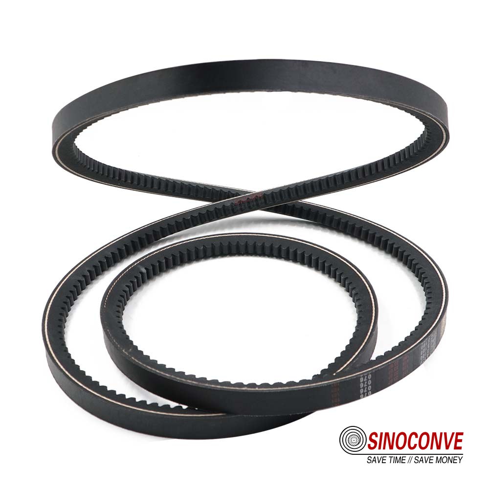
On a wrapped belt the bottom face is a fabric jacket and the rubber behind it never sees daylight — the first sign is usually a single deep crack, then neighbours appear. On a raw-edge cogged belt the mechanism is the same but the location changes: the cogs open and close like an accordion, and the failure appears as splits at the cog roots. The two are often confused on the bench, because a spent wrapped belt and a spent cogged belt look similar once the cover is gone.
Where the two differ matters commercially. Cogged belts tolerate a smaller pulley — commonly quoted at 30 to 40 percent below the wrapped minimum — and they run cooler because the cogs give the belt somewhere to flex without generating the same internal heat. The trade is that the raw edge has no fabric armour against abrasion and oil, so on a dust-loaded drive a cheap cogged belt can wear out on the flanks before fatigue ever becomes the issue. Our engineers compared the two constructions in detail in the classic versus cogged belts comparison.
The Number That Decides It: Datum Diameter Against Belt Height
Measure the datum diameter of the smallest grooved pulley, then compare it with the minimum the belt maker lists for that profile. Datum diameter is not outside diameter. For a sheave with a groove depth of 12 mm, a 120 mm outside diameter gives a datum diameter near 96 mm, and that 24 mm difference is the entire argument. Measure the groove depth with a depth gauge at the deepest point, then subtract twice the depth from the outside diameter.
If the drive is running a section that is too tall for its pulley, the honest fix is a smaller section, not a tougher belt. Dropping from a B section at 17 mm top width to an SPB at 16.3 mm buys only 0.7 mm. Dropping to an SPA at 12.7 mm, or moving to a cogged belt of the same profile, changes the flex behaviour far more.
| Section | Top width | Height | Min. datum dia., wrapped | Min. datum dia., cogged |
|---|---|---|---|---|
| Z | 10 mm | 6 mm | 50–63 mm | about 40 mm |
| A | 13 mm | 8 mm | 71–90 mm | about 63 mm |
| B | 17 mm | 11 mm | 112–140 mm | about 90 mm |
| C | 22 mm | 14 mm | 180–224 mm | about 140 mm |
| D | 32 mm | 19 mm | 315–355 mm | about 250 mm |
| SPZ | 9.7 mm | 8 mm | 63–71 mm | about 50 mm |
| SPA | 12.7 mm | 10 mm | 90–112 mm | about 71 mm |
| SPB | 16.3 mm | 13 mm | 140–180 mm | about 112 mm |
| SPC | 22 mm | 18 mm | 224–280 mm | about 180 mm |
| 3V | 9.5 mm | 8 mm | about 63 mm | about 50 mm |
| 5V | 15.9 mm | 13 mm | about 140 mm | about 112 mm |
| 8V | 25.4 mm | 23 mm | about 280 mm | about 224 mm |
Figures are the ranges we see quoted across published catalogue data. The belt and sheave maker's own table governs any specific drive.
Two multipliers catch most of the remaining fatigue failures. A flat back-side idler should be at least 1.25 times the datum diameter of the smallest grooved pulley, and it should never be smaller than the smallest grooved pulley in the drive. A drive running a back idler at 80 mm against a 90 mm grooved pulley will eat cog roots from the outside in, and no belt compound will stop it. As a maker of both V-belts and the rubber conveyor belt that shares the same plant floor as these drives, we can tell you the geometry argument is always cheaper to settle than the material argument.
04Mode 2: Top Cover Lifting and Edge Fraying
The back of the belt is the part nobody looks at until it is too late, and it is the part that fails first on a hot or oily drive. There is nothing on the back to protect it. On a wrapped belt the cover is a single fabric jacket bonded to the top cord; on a cogged belt the back is bare rubber with a tie-band or nothing at all.
Heat and Oil Attack the Cover First
Rubber compounds behave in opposite directions as temperature climbs. Below roughly 60 °C ambient, a standard wrapped industrial belt is comfortable. Push the drive into 75 °C air next to an unlagged pipe and the compound starts to harden; the cover loses elasticity, hairline cracks appear across the back, and eventually the fabric lifts in sheets. Oil does the reverse. A drip from a gearbox seal softens the cover, the bond line weakens, and the edge frays into loose cords within a few hundred hours.
You can separate the two causes without a lab. Heat-hardened rubber feels brittle and cracks when you bend a 200 mm length back on itself; a thumbnail leaves no mark. Oil-softened rubber smears, deforms under the same thumbnail and leaves a dark residue on your fingers. Wipe the groove with a white rag — a black smear with a solvent smell is a seal problem, not a belt problem.
Gearbox case temperature is the fastest number to take. Touch a contact thermometer to the housing, not the belt, and compare it with ambient. More than 25 °C of rise on a normally loaded drive means the heat source is close to the belt path, and the belt is being used as a heat sink. Where ambient genuinely exceeds 60 °C, an EPDM-based heat-resistant construction is the ordinary answer, and our engineers built the same compounding experience into the heat resistant conveying line we supply for clinker and sinter duty.
Reading the Edge Wear Pattern for Misalignment
Misalignment has a signature that heat does not: it is asymmetric. One edge of the belt is frayed, the other is clean. The sidewalls are polished on one side only, and the polish runs from top edge to bottom edge in a band rather than all over. Look at the sheave flanges as well. A belt running hard against a flange will polish a ring into the flange face and eventually wear a groove into it.
Two numbers govern this. Angular misalignment between shaft centrelines should stay under about half a degree; parallel offset should stay under roughly 0.5 mm for every 100 mm of centre distance. Half a degree sounds trivial and is not. On a 500 mm centre distance it displaces the pulley face by nearly 9 mm, which is more than the full top width of a B section belt. Nothing that far out of plane will run without taking a set.
Use a straightedge held against both pulley faces, checked on the front face and again on the rear. Then check with a laser or a taut wire if the centre distance exceeds a metre, because a straightedge stops being honest at that length. As a V-belt manufacturer we get blamed for a lot of belts that were simply installed on drives that were never in plane to begin with.
05Mode 3: Clean Transverse Break
A belt that parts in a clean line, with cords snapped flush and very little fraying, was not worn out. It was overloaded.The distinction matters because the repair is completely different.
Overload, Jam or a Foreign Object
Fatigue cracks grow over weeks. An overload break happens in under a second. The cord bundle shears at one point, the belt snaps back, and if the motor is still energised the broken ends whip around the pulley and melt or polish themselves against the groove within a few revolutions. When you see melted ends alongside a clean break, the drive kept running after the failure, and the operator probably heard it.
Four causes cover most cases. The driven machine jammed — a mixer drum with a lump of aggregate wedged between blade and shell, a screw conveyor packed solid. A direct-on-line start was used on a drive that should have been started on a soft starter or a star-delta, so the belt absorbs the full locked-rotor torque for the first second. A foreign object passed through the groove, denting the belt as it went. Or the belt was simply under-sized for the duty and ran at 100 percent of its rated capacity for years with no margin left.
What to Measure After a Break
Start with the two flanges of the driven pulley. Run a finger along the flange inner edge and you will find the nick — a burr of half a millimetre is enough to shave a cord bundle in a few thousand revolutions. Then check the belt itself for a single strand standing proud at the break. That strand failed first, and where it sits tells you whether the belt was running against a flange or through a groove that had collected debris.
Then look for the machine's own evidence. Ask for the ammeter log for the shift, ask whether the jam happened before or after the belt broke, and ask what the operator heard. On a drive behind a jaw crusher or a feed hopper, a belt break is usually the third event in a sequence, not the first. We build V-belts in the same plant where we run our conveyor belt manufacturer operations, and on both product lines the rule is identical: find out what stopped turning before you decide what broke.
The fix, once you have found the jam, is rarely to buy a stronger belt. Add a belt to the set if the drive has a spare groove. Fit a shear-pin or a torque-limiting coupling on the driven side. Correct the starting method so the first second of torque does not arrive as a shock. And check the belt count against the drive rating: a four-groove sheave running three belts has already told you the story.
06Mode 4: Slip, Glazing and Burning
Slip is the failure operators notice first and diagnose last. It announces itself with a shriek at start-up, then a burning smell that hangs in the drive room for a week. By the time a belt is glazed, the surface that is supposed to grip has been converted into something closer to polished stone.
The Sound and the Smell Tell You First
Rubber generates grip by deforming into the groove wall. Once the surface hardens, that deformation stops and the belt slides instead of gripping. Friction heat then raises the sidewall temperature until the compound degrades further — a loop that runs away in minutes on a heavily loaded drive. A glazed belt is hard and shiny in bands, and if you press a thumbnail into the sidewall the indentation stays. Fresh rubber springs back.
Two causes produce the identical symptom, and telling them apart takes one wipe of the groove. Contamination — oil mist, cement dust mixed with water, a leaking hydraulic hose above the drive — reduces the friction coefficient directly. Low tension reduces the normal force the belt can apply. If the groove is dry and clean but the deflection reading is out of spec, it is tension. If the groove is coated, fix the leak first and re-tension afterwards, because the belt that was tensioned to compensate for a greasy groove will be badly over-tensioned on a clean one.
There is a third cause that is easy to miss: the belt is not the right profile for the groove. Sitting an A section in a B groove is a common site error, and the belt will grip on its bottom corner, sink too deep, and slip under load while looking perfectly healthy.
Field note from our engineers: A sand screw drive at an aggregate yard kept shredding A-section belts in roughly 900 hours. The maintenance team had been tightening them further each time the belt slipped, which worked for a fortnight and then broke the belt. We measured the driven sheave: 82 mm datum against a wrapped minimum of about 90 mm, and the groove had opened to roughly 0.7 mm oversize on top of that. Two changes fixed it — a reground sheave and a cogged belt of the same profile, tensioned to the maker's table rather than to feel. That set ran past 5,000 hours. The lesson was not that cogged belts last longer. It was that the drive had been asking a wrapped belt to grip a groove it never fit.
Deflection: The Only Tension Check Worth Doing
Finger pressure is not a measurement. The deflection method is: mark the belt mid-span, place a steel rule behind it, apply a known perpendicular force and read how far the belt moves. The target deflection is about 16 mm for every 1,000 mm of span, which is the same as 1/64 inch per inch of free span. Force is applied per belt, and the belt must be stationary and free of dust.
Two details decide whether the reading means anything. Measure on the longest free span, never next to a pulley. And use the used-belt force rather than the new-belt force once a set has been running for a few days, because a belt that has taken a set sits at a lower tension for the same deflection when it is fresh out of the box.
| Section | Deflection target | Force per belt, new set | Force per belt, run-in set |
|---|---|---|---|
| SPZ / Z | 16 mm per 1,000 mm span | 15–22 N | 11–17 N |
| SPA / A | 16 mm per 1,000 mm span | 25–40 N | 19–31 N |
| SPB / B | 16 mm per 1,000 mm span | 45–70 N | 34–55 N |
| SPC / C | 16 mm per 1,000 mm span | 80–120 N | 60–95 N |
| D section | 16 mm per 1,000 mm span | 130–180 N | 100–140 N |
| 5V / 8V | 16 mm per 1,000 mm span | 45–70 N / 110–170 N | 34–55 N / 85–130 N |
Indicative bands compiled from commonly published drive data. Always tension a specific drive to the belt maker's own table, which knows the arc of contact and the duty factor.
Re-check tension 24 to 48 hours after a new set goes on, and again after the first week. A belt that has lost its tension in that window has usually bedded into a worn groove rather than stretched, and that is the moment to measure the sheave. When you are replacing a set, ordering the belts and the sheaves together from one conveyor belt supplier and belt maker saves the argument about which part caused the failure.
07Mode 5: Elongation Beyond Limit
Every belt stretches. The cord bundle takes up load in the first hours and settles, then creeps slowly for the rest of its life. The failure is not stretch. The failure is a slide rail with nowhere left to travel and a tension screw already at the end of its thread.
Stretch Is Normal; Running Out of Take-Up Is Not
Most wrapped industrial V-belts are quoted at roughly 1 to 2 percent elongation during run-in, and drive frames are usually built with 3 to 4 percent of take-up travel to absorb it. Once permanent stretch passes about 4 percent of datum length, the slide is normally out of travel and the set is finished. A belt in that condition still looks whole. It is simply sitting deep in the groove with no tension, slipping under load and heating up, which is why elongation so often gets misread as a slipping problem.
Two things imitate stretch. A worn groove lets the belt sit deeper, and the effective pitch circumference grows even though the belt has not moved. Thermal growth on a long drive frame does the same thing as ambient swings. Before you condemn a set, look at the take-up travel left and at the sheave condition. If the slide still has 30 mm of travel remaining, the belt is not the problem.
How to Measure Elongation Without a Datum Length
The clean method is to lay the belt flat on a clean floor, pull it straight by hand until the sides just touch, and measure the outside length with a tape against the length stamped on the back. A difference over about 1 percent in a matched set is enough to make the set pull unevenly. If the stamp is gone, fit the belt on the drive, mark a point on the belt and a fixed point on the frame, apply running tension, turn the drive 100 revolutions, and measure how far the mark has moved. Repeat the same test on a new belt of the same length and you have a comparison that does not depend on any catalogue.
Where the elongation is real, the cause is usually the cord construction rather than the cover. A belt built with fewer, thicker cords stretches more under the same load. That is one honest reason a very low V-belt price ends up costing more per running hour, and it is worth checking the cord specification rather than the cover when you compare quotations. Belts made to a specific standard usually carry a minimum cord strength requirement, which is a more reliable screen than the price line.
08Mode 6: Groove Wear and Profile Mismatch
Grooves wear in a way that hides itself. The belt still fits, the drive still runs, and the only outward sign is that the belt sits a little lower than it used to. By the time anyone measures, the geometry has been wrong for a year.
Groove Angle: 34, 36 and 38 Degrees
The groove angle is not a machinist's preference. It comes from the way a belt's cross section deforms as it wraps a pulley. On a small pulley the belt bends sharply, its cross section is squeezed, and the wedge that seats in the groove becomes effectively narrower, so the groove must be cut at 34 degrees. On a large pulley the belt is nearly straight and the groove is cut wider, at 38 degrees. The middle band uses 36 degrees. Run a belt in a groove that is too wide and contact moves to the bottom corners; the belt sinks, the wedging action collapses, and the belt slips and then cracks from the flank inward.
| Section | 34° groove used up to | 36° band | 38° above |
|---|---|---|---|
| SPZ / Z | about 80 mm datum | 80–118 mm | 118 mm |
| SPA / A | about 118 mm datum | 118–190 mm | 190 mm |
| SPB / B | about 190 mm datum | 190–315 mm | 315 mm |
| SPC / C | about 315 mm datum | 315–560 mm | 560 mm |
| D section | about 500 mm datum | 500–800 mm | 800 mm |
Indicative bands aligned with the way sheave makers publish groove tables. Always check the sheave maker's data for the exact cut.
Three Ways to Measure a Groove in the Field
The fastest check needs no instrument. Drop a new belt into the groove and look at where its top edge sits relative to the pulley rim. A correctly sized belt sits with its top surface roughly flush with the rim, or a millimetre or two proud of it. When the top edge sinks more than 1.5 to 2 mm below the rim, the sheave is worn or the wrong profile is in the groove, and one of those two is going to destroy the next set as well.
For a number rather than an impression, use a groove gauge if you have one, or a vernier across the groove at three points around the circumference. A spread of more than about 0.5 mm between readings means the groove is out of round as well as oversize, which usually points to a bearing or a shaft problem upstream. A ball or plug gauge of the correct nominal size is the traditional check and costs very little.
Field note from our engineers: In a 42 °C clinker gallery we were asked to explain why an SPB drive was burning through a matched set every three months. Nothing looked wrong until we gauged the driven sheave. Nominal groove angle was 38 degrees; it measured close to 40.5 degrees, and the groove width was 0.6 mm oversize. The belts were sinking about 2 mm below the rim, so they were gripping on their bottom corners instead of their flanks. Regrinding the sheave and resetting the set to the used-belt tension figure took the drive from a set every 3 months to a set every 14 months on the same duty. The belt had never been the failing part.
A groove gauge across a worn sheave. Oversize by 0.6 mm is enough to kill a set every quarter.
Worn sheaves are cheap to fix and expensive to ignore. A regrind costs less than three replacement sets, and once the angle is back inside tolerance the belt runs where it was designed to run. Where a plant runs several drives of the same size, we often see the sheaves swapped out together while a conveyor belt distributor delivers the new belts in the same visit, which keeps the geometry and the belt matched.
09Mode 7: A Matched Set That Was Never Matched
Six belts on six grooves are supposed to share the load equally. In practice they share it inversely to their length. The shortest belt in a set is the one in contact first, so it carries more tension, runs hotter, stretches faster, and fails first. Then the remaining five inherit its share of the load and follow within a few weeks.
Why One Belt Out of Six Dies First
An operator who sees one broken belt and five healthy ones usually concludes that the broken one was defective. That reading is backwards. The five survivors are the evidence: they were longer, they idled, and they were still fine when their neighbour died. If a single belt in a set fails while the rest look almost new, the set was out of tolerance from the day it was fitted.
The usual cause is mixed purchasing. Two belts from one production batch and four from another, or a replacement added later from a different brand with the same nominal designation but a different cord construction. Nominal size repetition is not the same as length matching. A set that differs by 0.5 percent in length will load the shortest belt disproportionately and cut set life by more than half.
How to Check a Set Before It Goes On
Lay all belts of the set side by side on a clean floor, pull them straight and compare the match marks if they carry them, or measure each one with a tape. Reject any set with more than about 0.15 percent spread across the shortest to longest. Do not mix constructions either; a wrapped belt and a cogged belt of the same nominal section do not stretch alike and will fight each other on the same drive. Where a drive is prone to belt flip and unequal loading, a banded construction ties the individual belts together with a top tie-band and removes the problem at the source, which our engineers covered in the banded V-belt drive selection guide.
When you order, order the whole set from one batch and keep the belts together with their batch identification until they are fitted. Plants that buy from a single source and hold a small matched-set stock avoid most of this failure mode entirely, which is one reason maintenance planners consolidate onto one wholesale conveyor belts and transmission program rather than buying belt by belt as each drive fails.
10Mode 8: Why a V-belt for Concrete Mixer Drives Fails Early
Mixer drives deserve their own section because they combine more failure drivers in one small package than any other drive we see. A V-belt for concrete mixer duty is not a general-purpose belt in a special place; it is a belt asked to survive a duty cycle that punishes every part of the construction at once.
The Duty That Makes Mixer Drives Different
Start with the load. A drum holding a wet batch of 1.5 cubic metres carries well over two tonnes of material, and the drive has to accelerate it from rest. Locked-rotor torque at the moment of start can be three to five times running torque on a direct-on-line motor, and that shock arrives through the belt before anything else in the train feels it. Then there is inertia: the drum shell and its strengthening ribs are a flywheel, and on a reversing drive the belt sees the drum's stored energy handed back to it every time the drum is reversed for discharge.
Add the environment. Cement dust is fine, alkaline and mildly abrasive. It settles into grooves and mixes with water splash from the wash-down hose to form a paste that both lubricates the groove and grinds the sidewall. Dust in a groove does not look like a problem, and it acts like a lapping compound against the one surface the whole drive depends on.
Add the geometry. The speed reduction from a four-pole motor at about 1,450 rpm to a drum turning at 15 to 20 rpm is enormous, so most mixer drives stage the reduction across two or three belt steps with small driver sheaves at each stage. A 100 mm sheave on a B section is right at the edge of the wrapped minimum. This is precisely where a cogged or raw-edge construction earns its place, and where the difference between a wrapped and cogged belt stops being a preference.
Finally, the duty cycle itself.A mixer starts and stops dozens of times a shift, reverses for discharge, and often restarts against a partially settled load. Static creep under that pattern is much faster, so tension is lost sooner, so the belts slip, so they get tightened, and the sheaves wear faster than they would on a steady drive of the same power.
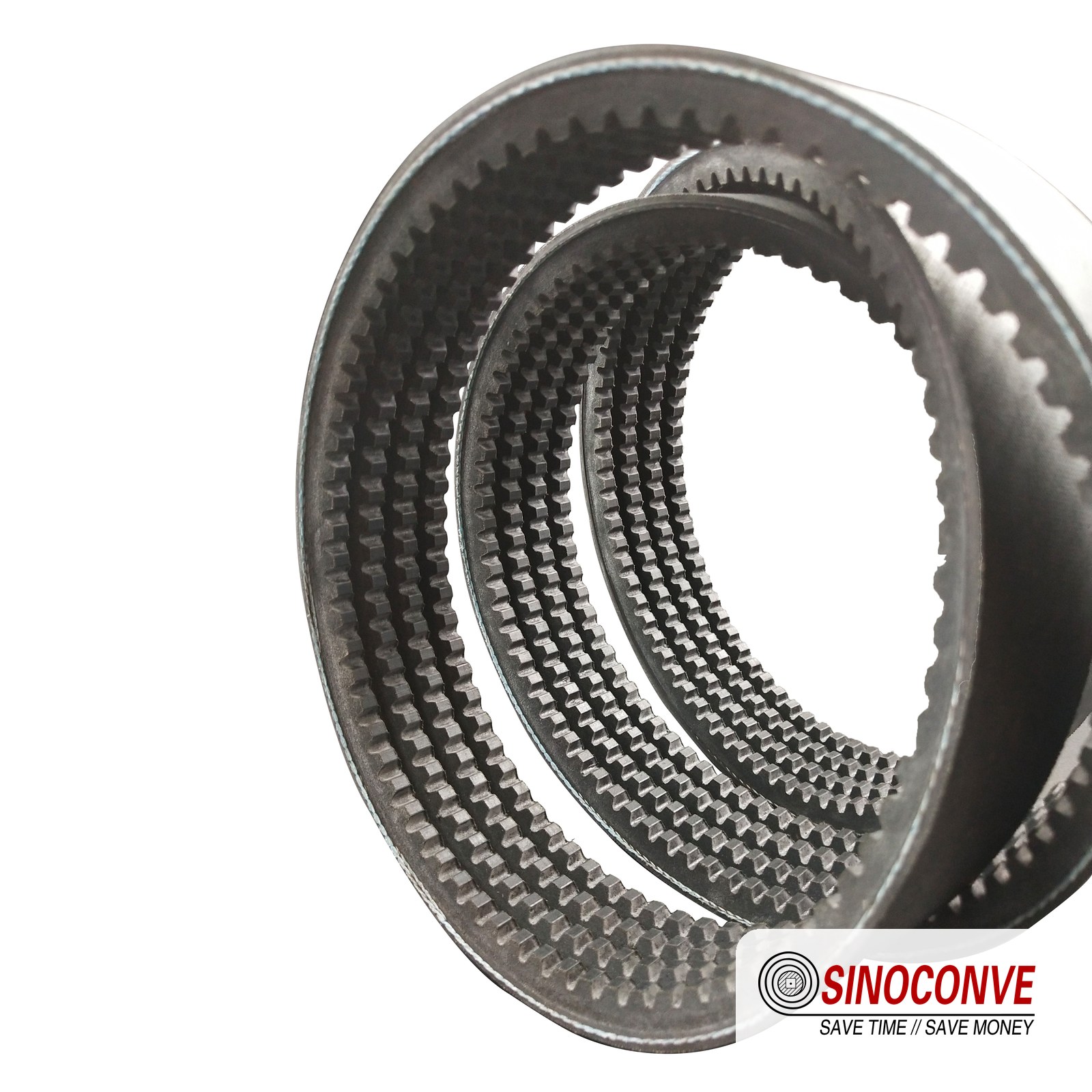
A banded set on a reversing mixer stage. The tie-band is what stops individual belts rolling over.
A Failure Signature Checklist for Mixer Sets
Mixer failures cluster tightly once you know what to look for. The table below is the one we hand to plant fitters when they call about a drum drive.
| Symptom on the drum drive | What it usually means | Check before ordering | Typical hours |
|---|---|---|---|
| Evenly spaced bottom cracks on the first-stage set | Driver sheave too small for the section | Datum diameter of the motor sheave against the catalogue minimum | 300–800 |
| Hard glossy flanks with grey paste packed in the groove | Dust and wash-water contamination | Wipe the groove with a white rag; trace the wash-down spray path | 200–1,500 |
| Tie-band torn on a banded set | Belt flip during the reversing cycle | Alignment of all sheaves, groove wear, slack-side vibration | 500–2,000 |
| New set fails within a fortnight of fitting | Matched set out of tolerance or wrong profile | Lay the whole set flat and measure; verify the profile stamp | Under 100 |
| Belts walking off the sheave under full batch load | Drum bearing play or frame movement | Dial gauge on the drum bearing housing; check the frame for cracks | Anytime |
| Burning smell at every start, belts still gripping when cold | Over-tensioned to chase an earlier slip | Mid-span deflection against the maker's table | 100–600 |
| Brittle, dust-caked, cracked back on a hot plant | Ambient heat plus ozone ageing | Ambient and gearbox case temperature; ventilation path | 1,000–4,000 |
The Repairs That Hold on a Mixer Drive
Four things move the needle. Move the first-stage driver up in diameter where the frame allows, or switch to a cogged construction of the same profile where it does not. Fit banded belts on the reversing stage, because a tied set will not roll over the way six loose belts will. Guard the grooves with a simple sheet shield so the wash-down hose stops spraying the belt path. And set tension from the maker's table, then re-check it after 48 hours — not by feel, not by sound, and not by how far the belt moves when you push it.
Where the drum has a soft-foot or bearing problem, fix it first. No belt construction survives a driven shaft that moves 0.4 mm as the batch turns.
Field note from our engineers: A ready-mix plant went through two complete banded sets in three months on a reversing drum drive and had started to blame the belts. We watched two starts. On each reversal the slack side of the set lifted and the tie-band clipped the guard. The plant had added a home-made guard 20 mm too close to the belt line, and every reverse cycle took a bite out of it. Grooves were within tolerance, tension was right, belts were the correct profile. We moved the guard 20 mm and the third set ran eleven months. Diagnosis is often a matter of watching the machine do the thing that breaks the belt.
11Mode 9: Oil, Heat, Ozone and Cold
Some drives fail because of what the belt does. Others fail because of where the belt lives. Environmental failure is slow, quiet and easy to mistake for ordinary wear, and it is the one mode where changing the compound is a legitimate answer rather than an excuse.
Four Environmental Killers and Their Signatures
Heat hardens and then cracks. Standard rubber constructions are usually comfortable to about 60 °C ambient, and a drive sitting beside an unlagged steam line or inside a closed enclosure will push past that on a warm day. The signature is a brittle back with fine cracks running across it and a cover that lifts in flakes when you bend the belt. Heat-resistant EPDM constructions are commonly specified up to around 100 °C, and lower ambient is always cheaper than higher temperature resistance.
Oil softens and swells. The flanks become dished and slack-looking, the cover lifts at the edges and the belt leaves a black smear on a rag. Nitrile and polychloroprene compounds resist it far better than a general-purpose rubber, though the correct fix is still the gearbox seal.
Ozone cracks a belt that is standing still. A spare set left under tension on a frame, or an installed belt on a standby drive, will show a network of small cracks across the back within a season when it sits near an electric motor or a drive enclosure. Those cracks propagate to the cord line, and a belt that has been sitting unguarded for two years is not new stock even if it has never turned.
Cold stiffens. Below about minus 18 °C, a standard belt hardens, and a cold start on a hardened belt can crack the bottom face in a single revolution. Cold-duty constructions extend the working range further down, but the more useful step on a winter start-up is to let the drive turn over slowly before loading it.
What the Belt Says About Where It Has Been
The damage pattern is often enough to reconstruct the environment from a photograph. Cracks on the back only, with clean flanks, points to heat or ozone and a belt that spent time standing still. Flanks worn bright and dished with lifted cover points to oil. Cracks concentrated on the bottom face with intact sidewalls points to geometry rather than chemistry. Dust embedded in the flanks in a band, rather than evenly, points to an abrasive environment and probably a shield that only covers part of the belt path.
Where the enclosure itself is the problem, ventilation is usually a cheaper fix than a more expensive compound. We have walked through enough plants to say that a drive room with a working extractor fan goes through fewer belts than one without, regardless of what the belts are made of. As a conveyor belt factory that supplies both belt families, we see the same pattern on drives in quarrying and mining duty and in covered warehouse and logistics installations, where the belts are smaller but the ambient conditions are just as punishing.
12The Field Kit and a Ten-Minute Checklist
Diagnosis is a measurement discipline, and the kit is small. A 300 mm steel rule, a 1 m straightedge, a vernier calliper, a groove or ball gauge, a spring scale reading to 200 N, a dial gauge on a magnetic base, an infrared thermometer and a chalk. That is enough to run every check in this article.
What to Carry and What to Compare Against
Carry the sheave data as well as the belt data, because half of these thresholds are geometry and not material. If the drive has no documentation, photograph the sheave stamp and the belt stamp before you leave site; those two images settle most arguments about who supplied what.
The Ten Checks, In Order
| Check | Tool | Threshold we work to |
|---|---|---|
| Groove width | Vernier or groove gauge, three points | Within 0.5 mm of nominal; spread under 0.5 mm |
| Belt sink in groove | A new belt of the correct section | Top edge not more than 1.5 mm below the rim |
| Deflection | Steel rule plus spring scale, longest span | 16 mm per 1,000 mm at the maker's force |
| Alignment, front and back faces | Straightedge, taut wire or laser | Angular under 0.5°; offset under 0.5 mm per 100 mm |
| Sheave runout | Dial gauge on the flange face | Under 0.25 mm total indicated |
| Shaft and bearing play | Dial gauge, or a pry bar and a feeler | Under 0.1 mm radial |
| Temperature | Infrared thermometer, belt and housing | Housing under ambient plus 25 °C |
| Oil and dust in the groove | White rag | No smear, no grit that feels like sandpaper |
| Matched set spread | Tape measure, belts laid flat | Under 0.15 percent shortest to longest |
| Take-up travel remaining | Tape measure on the slide | At least 30 percent of original travel |
Run the checks in that order and most drives are diagnosed before the last three. Each one takes under a minute on a drive with the guard off, and the whole sequence costs less than one replacement set. The numbers above are the thresholds we work to in the field; where a drive has documentation, the drive's own data wins.

13Frequently Asked Questions
How do I tell a fatigue failure from an overload failure?
Look at the cord ends. Fatigue gives you many small cracks growing over weeks, evenly spaced across the bottom face or the cog roots, with the top cover still attached. Overload gives you one clean break, cords sheared flush, and sometimes melted ends where the drive kept running after the belt parted. A fatigue belt has a history. An overload belt has a moment.
Is only one belt of my set failing a sign of a bad belt?
No. It usually means the set was not matched. The shortest belt carries the most load, runs hottest and fails first, while its longer neighbours stand there looking almost new. Measure all of them laid flat on a clean floor before you order a replacement, and reject any set with more than about 0.15 percent spread.
What deflection should I set on a concrete mixer drive?
The same rule as any other drive: about 16 mm of mid-span deflection for every 1,000 mm of free span, applied with the force your belt maker lists for that section. What differs on a mixer is how often you check it. Start-stop and reversing duty works tension out of a set quickly, so re-check 24 to 48 hours after fitting and again after the first week.
Why is the back of my belt cracking while the flanks look fine?
That is heat or ozone, not load. A standard rubber construction is comfortable to roughly 60 °C, and a belt sitting under tension near a hot housing or an electric motor will develop fine cracks across the back within a season even if it never turns. Brittle, flaking cover means heat; a fine crack network on a belt that has been standing still means ozone.
Can I run a cogged belt on a drive that was designed for a wrapped one?
Usually yes, and on a small pulley it is often the better answer, because cogged constructions tolerate a datum diameter roughly 30 to 40 percent smaller. The caveat is abrasion. A raw edge has no fabric jacket, so on a dusty drive the flanks can wear out faster than a wrapped belt's would, which is why we ask what the environment looks like before recommending the swap.
How can I tell a worn groove without a gauge?
Drop a new belt of the correct section into the groove and look at the rim line. If the belt's top edge sits more than about 1.5 mm below the pulley rim, the groove has opened or the wrong profile is fitted, and the next set will fail the same way. A white rag wiped through the groove will also tell you whether you are looking at geometry or contamination.
How long should a V-belt last?
On a clean, aligned, properly tensioned drive, wrapped industrial belts are commonly quoted at 10,000 to 25,000 running hours. A dusty mixer or crusher drive is a different world, and 2,000 to 8,000 hours is realistic there. If you are losing sets in hundreds of hours, stop buying belts and start measuring the drive.
Should I replace the sheave at the same time as the belts?
If the groove measures more than 0.5 mm oversize, yes. A regrind or a new sheave costs less than three replacement sets, and fitting new belts into a worn groove simply transfers the cost of the sheave into the belt budget. Check the take-up travel too; a slide with under 30 percent of its travel left has no room for a fresh set to bed in.
Does over-tensioning ever help a slipping drive?
Only long enough to hide the cause. Extra tension raises bearing load, hastens bottom-face fatigue and shortens shaft and bearing life, while the belt keeps slipping on the contaminated or worn surface that started the problem. If the deflection reading is in spec and the belt still slips, the fault is in the groove, the profile or the load, not in the setting.
One habit separates plants that fight the same failure every quarter from plants that fix it once. Photograph the belt before you clean it, measure the groove before you order anything, and write the two numbers on the work order. When that drive fails again in two years, the note will tell the next engineer whether the geometry was ever corrected, and that single sheet of paper is worth more than any belt comparison you will ever run.
Related Products You May Need
- V-belts — wrapped, cogged and banded industrial V-belts in Z, A, B, C, D and SPZ to SPC.
- Timing belts — positive-drive synchronous belts for mixer and process drives where slip is not acceptable.
- Rubber conveyor belts — for the conveying side of the same plant.
- Heat resistant belt — clinker, sinter and cement duty where ambient heat kills standard compounds.
- Chevron and patterned belts — inclined conveying with material that will not sit still on a smooth surface.
- PVC conveyor belts — light-duty lines, packing halls and covered installations.
Related Blog Posts
- Choosing and maintaining a V-belt drive — installation and upkeep.
- V-belt buying guide: profiles and sizes — how to identify a section and specify a replacement.
- Classic V-belts vs cogged belts — when the flex behaviour of a raw-edge cog matters.
- Raw edge cogged V-belts for industrial drives — selection criteria and limits.
- Banded V-belt drive system selection — sets that will not flip under reversing load.
- Cogged V-belt maker vs wrapped supplier — what the construction difference means in practice.
- Engineering calculations for belt drives — the numbers behind tension, arc of contact and duty factor.
- V-belt and conveyor belt FAQs — short answers to the questions buyers ask most.