
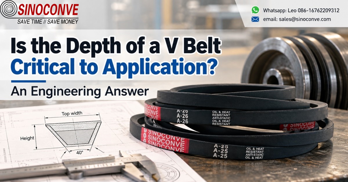
Short answer: the depth of a V belt rarely wrecks a drive on its own. It is, though, the usual reason a drive ends up under-rated, runs hot, or slips on the sheave that was already bolted to the frame.

Torque travels through the two angled flanks seated in a matched groove, so belt height decides how much flank engages and at what strain it bends around the smallest pulley. Depth turns decisive once the datum diameter falls below about 120 mm, once a groove is re-cut or worn wide, or once the wrong section is dropped into an existing sheave. On a 300 mm pulley a millimetre of extra height is a footnote. On a 75 mm sheave at 2,900 rpm that same millimetre decides between 4,000 hours and 600. Under a transmission belt manufacturer relationship, seating position and the height-to-diameter ratio are the first two numbers we check.
01Direct Answer: When Depth Is Critical and When It Is Not
Depth matters only while it moves the belt inside the groove
Depth matters only while it changes the belt's radial position inside the groove, and it stops mattering the moment the flanks are fully engaged with the base still clear of the floor. Whether the section stands 8, 10 or 13 mm tall follows from that seat and from the bend on the smallest pulley.
Small pulleys lead, because bending strain scales roughly with belt height over pulley diameter. A millimetre of extra height is noise on a 900 mm driven pulley. On a 75 mm pump pulley at 2,900 rpm the belt flexes 48 times a second, and the step from 8 mm to 11 mm of section is the step from survival to cracking along the base beside the cord. Worn grooves attack the same seat from the side; once groove and belt flanks both wear, the base touches down and the flanks unload.
Long centre distance, a large pulley and low speed push depth far down the list. A 22 x 14 mm C section running 300 mm to 450 mm at 600 rpm works at a bending severity of 14 / 300 = 0.047, so what matters on that drive is length, matched-set consistency and true groove angles.
When the seat is small, worn or mismatched, depth decides. A datum diameter under 120 mm is read through the height-to-diameter ratio and cracking along the back of the belt. A re-cut or unmarked sheave is read through groove width at the datum line against the seat height of a new belt. A classic section dropped beside a narrow one is read through top width against groove width and remaining base clearance.
The other three conditions push depth well down the list, and the work moves onto the drive as a whole. A short centre distance running three or more pulleys cares about total wrap angle and the accuracy of the belt length rather than the standing height of the section. Pulleys above 300 mm turning below 900 rpm make depth a weak factor, so tension, alignment and matched-set length tolerance take over, because the belt simply is not bending hard enough for height to matter. A banded or multi-groove drive sharing one hub sits between those extremes, where length matching across the set and uniformity of groove depth decide how evenly the load is spread between the belts.
So depth is a seating problem on small drives and a wear problem on old ones. Both show up inside ten minutes with a groove gauge and a straight edge laid across the rim.
02Cross-Section Geometry 101: Top Width, Height, Wedge Angle and Groove Contact
Why the section narrows as it deepens, and where the datum line sits
A wrapped V belt is a trapezoid, catalogued by top width, overall height and a 40° flank angle, with the datum width about 0.3 to 0.4 of the height down from the top face carrying the pulley rating. Because the flanks taper 20° each side, the section narrows 0.728 mm per millimetre of depth (2 x tan 20°). An A section falls from 13 mm to 7.2 mm across its height, a B from 17 to 9, a C from 22 to 11.8.
Belts are moulded at 40° because that is the free-state angle, and bending one around a pulley drops the working angle, so grooves come cut at 34, 36, 38 or 40° by datum diameter, with small sheaves taking the wider angles. A belt that is perfect on a 400 mm sheave can therefore sit badly on a 90 mm one. The datum line itself is where the cord plane rides, and every rating table is indexed on the diameter measured there. Worn flanks let the belt sit lower, which shrinks the effective diameter and lifts output speed, so a drive whose output creeps up 1 or 2 percent in a year without a pulley swap is usually running worn grooves.
03The Wedge Principle: Why the Flanks Carry the Load, Not the Base
Why the flanks carry the load and the base does not
Tension presses the belt radially into the groove, and the angled flanks turn that push into a far larger normal force on the walls. At 600 N of radial clamping each flank carries 600 / (2 x sin 20°) = 877 N, so 1,754 N in total, where a flat belt under the same 600 N gives 300 N per side. The wedge factor is 1 / sin 20° = 2.92.
Grip is the wedge factor times friction times radial load, F = 2.92 x mu x Fr, and a clean rubber flank on machined steel starts near mu = 0.5, so 600 N radial pulls 877 N tangentially before slip. Height is absent from that equation on purpose. Once the base bottoms out the radial force passes to the floor, the 2.92 falls to 1.0, and no extra tension recovers the 300 N of grip left.
Bottoming out is progressive. The base touches first on the tight side of the wrap while the slack side still clears, so slip arrives in short bursts at peak load and the drive squeals only at start-up. Heat then glazes the flanks, mu slides from 0.5 toward 0.3, and the polished stripe along the base appears only after weeks of that.
04Depth and Effective Contact Height: Worked Example One
Setting the sheave, the wrap and the three sections
Take a 100 mm datum sheave with a 38° groove, driven at 1,450 rpm with 180° of wrap, and seat three matched belts in turn, a 13 x 8 mm A, a 17 x 11 mm B and a 22 x 14 mm C. A correct sheave leaves a new belt 1.5 mm proud, so useful height is section height minus that stand-out, and each millimetre gives 1 / cos 20° = 1.064 mm of flank per side. The contact arc is L = pi x D x (wrap / 360) = 3.1416 x 100 x 0.5 = 157.1 mm.
The A section then runs 8 - 1.5 = 6.5 mm of contact height, and 6.5 x 1.064 = 6.92 mm of flank per side gives 13.84 mm both, so 13.84 x 157.1 = 2,174 mm2, rounded to 2,170. The B gives 9.5 mm, 10.11 mm per side and 3,180 mm2, a lead of 1,010 mm2. The C gives 12.5 mm, 13.30 mm per side and 4,180 mm2, up 92.6 percent.
What the contact area does to pressure, wear and slip
Push the same 600 N of radial load through the A and the B and the A section sees 877 / 2,170 = 0.40 MPa against 877 / 3,180 = 0.28 MPa for the B, the same load pressing 32 percent softer. Coulomb friction ignores area, so wedge theory says they slip together. Flank wear tracks contact pressure instead, so the A section wears roughly 46 percent faster.
| Quantity on a 100 mm sheave, 180 degrees wrap | 13 x 8 mm (A) | 17 x 11 mm (B) | 22 x 14 mm (C) |
|---|---|---|---|
| Effective contact height after 1.5 mm stand-out | 6.5 mm | 9.5 mm | 12.5 mm |
| Flank length, both sides, per mm of height | 2.128 mm | 2.128 mm | 2.128 mm |
| Flank contact area on the sheave | 2,170 mm2 | 3,180 mm2 | 4,180 mm2 |
| Contact area relative to A section | baseline | +46.5 percent | +92.6 percent |
| Flank pressure at 600 N radial force | 0.40 MPa | 0.28 MPa | 0.21 MPa |
| Section area of the trapezoid | 80.8 mm2 | 143.0 mm2 | 236.7 mm2 |
| Mass per metre at 1.25 g per cm3 | 101 g/m | 179 g/m | 296 g/m |
Set allowable flank pressure at 0.30 MPa and the arithmetic becomes a capacity test. The A section holds 0.30 x 2,170 = 651 N per flank, and 651 N of tangential pull, where the B holds 954 N, so 4.9 kW against 7.3 kW at 7.6 m/s, with cord fatigue capping the smaller section first. Width mismatch is worse than it looks, because a belt narrows 0.728 mm per millimetre of height while a 38° groove opens only 0.689 mm (2 x tan 19°). A 17 x 11 mm belt forced into an A groove rides the rim corners on a millimetre of flank and can climb out under shock, while a 13 x 8 mm belt in a B groove drops its 2.5 mm of clearance and wedges on the floor at a third of design grip.
05Bending Strain and Minimum Pulley Diameter: Worked Example Two
The bending index, and the pulley diameter that sets it
Wrapping a pulley bends the section and stretches the back, and the bending strain at the extreme fibre is close to belt height over datum diameter, I = h / D. That is not the cord strain, but it is a fair measure of how hard the belt is worked in bending. On a pump drive at 2,900 rpm the belt flexes 2,900 / 60 = 48 times a second. A 13 x 8 mm belt on a 75 mm pulley gives 8 / 75 = 0.107, a 17 x 11 mm belt on the 112 mm pulley the catalogue asks for gives 11 / 112 = 0.098, and the same 17 x 11 mm belt on the 75 mm pulley gives 11 / 75 = 0.147.
Turning that index into life and into heat
Flex fatigue follows a steep power law. At an exponent of six, mid-range in the five to eight usually quoted, relative life scales as (I ref / I actual)^6, so 0.098 to 0.147 gives (0.098 / 0.147)^6 = 0.088, about nine percent of reference life, while 0.098 to 0.110 gives (0.891)^6 = 0.50. Heat compounds it, because the 17 x 11 mm belt on the 75 mm pulley raises strain squared by (0.147 / 0.107)^2 = 1.89 and flexing volume by 143.0 / 80.8 = 1.77, so it has to shed 3.34 times the heat.
| Profile | Height h | Typical minimum datum diameter | Bending index h / D | Relative flex-fatigue life if forced onto a 75 mm pulley, referenced to an 8 mm section |
|---|---|---|---|---|
| SPZ, narrow | 8 mm | 63 mm | 0.127 | 1.00 |
| A / 13, classic | 8 mm | 75 mm | 0.107 | 1.00 |
| SPA, narrow | 10 mm | 90 mm | 0.111 | 0.26 |
| B / 17, classic | 11 mm | 125 mm | 0.088 | 0.15 |
| SPB, narrow | 13 mm | 140 mm | 0.093 | 0.054 |
| C / 22, classic | 14 mm | 200 mm | 0.070 | 0.035 |
Divide the published minimum datum diameter into the belt height and every matched profile lands between 0.07 and 0.13, small sections at the top and heavy classic sections at the bottom. Re-run that division for one fixed 75 mm pulley and the retrofit answer appears. An 8 mm section keeps essentially all its flex life, a 10 mm section about a quarter, an 11 mm section about 15 percent, and 13 mm or deeper under 6 percent. So where a machine has room only for 75 mm while the torque wants 17 mm, add a groove to the shallower section, since three A belts outlast one B section on the same sheave.
06Bottoming Out: Conditions, Field Identification and Consequences
The condition, measured as clearance and sink
A belt bottoms out when its base reaches the groove floor before its flanks reach full engagement, and two numbers govern it, the 2 to 3 mm of clearance a new matched belt keeps at the base and the total sink it gains from flank wear and over-tensioning. On a drive with 2.5 mm of clearance, 0.35 mm of groove wear per flank adds 0.35 / tan 19° = 1.02 mm, and 0.5 mm of belt flank wear per side adds 0.5 / tan 20° = 1.37 mm. That is 2.39 mm against 2.5 mm, a belt still full width and still passing inspection while a tenth of a millimetre from failure.
How to see it on site, and what it costs if you leave it
Lay a straight edge across the sheave rim and a correctly seated belt stands 1 to 2 mm proud, while a top level with or below the rim means it has sunk. On a multi-groove sheave the most loaded groove sinks first, and its belt shows a bright polished stripe along the base with the rest still moulded and dull. Heat is the second signature, a hub 15 to 25°C hotter than its siblings.
Left alone, bottoming changes the failure mode of the whole drive. The belt rides the floor where friction is lower, glazes and stops carrying torque, the operator adds tension, and the extra radial load shortens bearing life while over-tensioned shafts bend and whine. On a duplex set the bottomed groove runs slower and the belts fight each other, so gauge the groove before fitting any replacement.
07Insufficient Depth: What Happens When Contact Area Falls Short
Slip and edge wear arrive before any gauge does
A belt too shallow for the duty slips before it wears at all, first at start-up, then at load peaks, then steadily, the slip at the exit of the wrap audible as a chirp that comes and goes with load. On a 15 kW fan drive at 1,200 rpm an operator hears it for two or three seconds at each start. The wrong fix follows. Glazing drops mu from 0.5 to 0.3, the operator tightens, the belt sinks onto the short part of the flank where grip is worse, and the loop ends in a shredded belt and a bearing.
When contact height is short the load concentrates on the top edge of the flank instead of spreading down it, edge pressure rises, and the upper corners polish to a shiny band within a few hundred hours, a belt worn 2 to 3 mm down from the top with its lower flank barely touched. On that 100 mm sheave each millimetre of effective height is worth 334 mm2, since 2.128 mm of flank span times the 157.1 mm arc gives 334. Lose one and you lose 15 percent of the 2,170 mm2 patch and lift flank pressure 18 percent.
Heat, rubber, and the point where depth becomes belt life
Flank slip of 0.5 to 1.5 percent of belt speed makes friction power directly. Take a drive with 600 N of tangential force and 1 percent slip at 7.6 m/s, where the slip velocity is 0.076 m/s and the friction power is 600 x 0.076 = 46 W, concentrated on a patch only a few thousand square millimetres across in a belt body of low thermal conductivity.
That figure is small in absolute terms, and 46 W still raises local surface temperature fast. Above roughly 70°C measured on the belt after shutdown, the EPDM and SBR compounds used in wrapped belts start losing tensile strength, and the rate accelerates from there. If you want a deeper look at how temperature and geometry interact with the cord, the companion article on V belt construction and load path walks through the cord and cover layers.
08Classic versus Narrow Sections: What the Depth Difference Really Buys
Same top width, more depth
The narrow section family was introduced precisely because classic profiles run out of grip on small sheaves. Compare A with SPA. The A section is 13 mm across the top and 8 mm tall. The SPA section is 12.7 mm across the top and 10 mm tall. The narrow belt is actually a shade narrower on top and 2 mm deeper, a 25 percent increase in height for the same footprint. The extra 2 mm goes straight into effective contact height once the belt is seated, which means more flank area, lower flank pressure and a smaller radial force required for the same tangential pull.
That is why narrow sections can carry 30 to 60 percent more power per belt at the same speed, depending on pulley diameter, and why they tolerate smaller pulley-to-belt height ratios. The price is a wider minimum diameter band in absolute terms, a more demanding groove tolerance, and a belt that is less forgiving of an abused sheave. Put an SPB belt in a badly worn B groove and it will not merely slip, it will hammer the groove walls, because the deeper flank engages further down where the wear is greatest.
For a deeper profile-by-profile comparison of the classic and narrow families, including how the datum widths map across the two systems, the team's earlier piece on classic and cogged V belts covers the cross-references in detail. What matters for depth is the single line in the table below: for a near-identical top width, the narrow section is 2 to 4 mm deeper.
| Profile | Top width | Height (depth) | Taper of the flanks | Flank length per side, full height | Power density for the footprint |
|---|---|---|---|---|---|
| Z / 10, classic | 10 mm | 6 mm | 0.728 mm per mm | 6.4 mm | Low |
| SPZ, narrow | 9.7 mm | 8 mm | 0.728 mm per mm | 8.5 mm | Moderate |
| A / 13, classic | 13 mm | 8 mm | 0.728 mm per mm | 8.5 mm | Low to moderate |
| SPA, narrow | 12.7 mm | 10 mm | 0.728 mm per mm | 10.6 mm | High |
| B / 17, classic | 17 mm | 11 mm | 0.728 mm per mm | 11.7 mm | Moderate |
| SPB, narrow | 16.3 mm | 13 mm | 0.728 mm per mm | 13.8 mm | High |
| C / 22, classic | 22 mm | 14 mm | 0.728 mm per mm | 14.9 mm | Moderate |
| SPC, narrow | 22 mm | 18 mm | 0.728 mm per mm | 19.2 mm | Very high |
When the classic section is still the right answer
Narrow profiles win on power density, but they lose when the drive is old, the sheaves are worn, or the maintenance team is not going to gauge grooves. A classic A or B section in a classic groove is a tolerant pairing: the shallower flank engages over a shorter height, so wear of 0.3 mm in the groove costs less of its contact area than the same wear costs a deep narrow belt. We still ship a lot of classic sections into cement plant auxiliaries and quarry screens for exactly that reason. The drives run 20 hours a day, sheaves get replaced only when they crack, and a belt that tolerates a tired groove is worth more than a belt with a higher rating.
09Depth versus Cogging: What Notching the Belt Actually Changes
Cogging changes flexure, not the wedge
A cogged or notched belt has transverse slots moulded into the underside of the section. Those slots remove material from the compression side, which lowers the belt's bending stiffness and lets it wrap a smaller pulley without the base buckling and cracking. That is the entire purpose. The slots do not add flank area, they do not increase the effective contact height, and they do not make the belt grip better. A 13 x 8 mm cogged belt in a groove for a 13 x 8 mm belt has the same wedge geometry as a wrapped belt of the same dimensions, and it should be tensioned to the same figure.
The confusion arises because cogged belts are often specified alongside small pulleys, so people attribute the improvement to the cogging when the real change was the pulley diameter or the section. If you are comparing a wrapped and a cogged belt of the same section, the notched version will run cooler on a small pulley because it bends more easily and generates less hysteresis heat through the base. It will not tolerate a badly matched groove any better, and it is slightly more sensitive to grit ingress because the slots hold debris against the compression side. Our full treatment of the construction differences, including when raw-edge cogged belts are worth the extra cost, sits in the article on cogged belt construction and selection.
Where a timing belt fits into the same decision
When a drive's problem is genuinely that the pulley is too small for a V section, the alternative is a synchronous drive, where torque moves through tooth engagement rather than wedge friction and the pulley diameter is set by tooth count rather than by wedge geometry. That is a different engineering decision and a different cost structure. As a timing belt manufacturer as well as a V belt supplier, we usually frame it this way: if the drive needs high power in a very short centre distance, synchronous is the honest answer, because a V belt of any depth is working against a bending limit that a toothed belt does not have in the same way. If the drive just needs more grip on an existing sheave, the fix is matching the section and grooving it correctly, not changing the drive family.
A note on raw-edge and banded variants
Raw-edge belts, banded sets and wide-section agricultural belts all keep the 40 degree wedge, so everything in this article applies to them without modification. The banded construction is worth one extra sentence because it interacts with the depth question. A banded belt ties two to five V sections together with a top cover, which prevents the individual strands from flipping or jumping in a worn groove, and it holds the set's effective diameter consistent across grooves. That is a real benefit on a sheave that is sagging into bottoming on one groove only. The construction is described in more detail in the piece on banded V belt drive selection, and the sourcing side in industrial distributor sourcing.
10Profile Depth Reference: The Numbers That Matter for Seating
Reading the code behind the belt
Every wrapped V belt carries a length code and a profile letter or digits, and the profile code is what you check against the sheave. On a classic section the letter or number tells you the top width; on a narrow section the three-letter code tells you the width and height together. Do not reverse-engineer the depth from the length number, which is measured along the pitch line and says nothing about the section. If you want the full cross-reference between codes, lengths and datum widths, our earlier reference table covers it in one place: V belt size and profile chart explained.
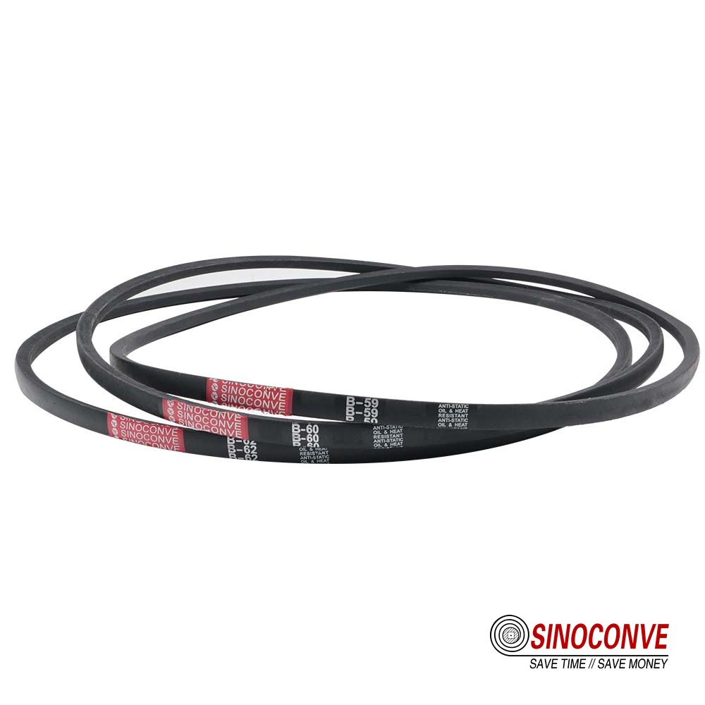
Depth-relevant columns only
The table below deliberately stops at the seating numbers and leaves length ranges, power ratings and datum widths to the profile references. What you need to convert a profile into a seating check is the height, the flank taper and the resulting base width, because the base width against the groove floor is the bottoming margin.
| Profile code | Height h | Base width at 40 degrees | Depth taper over the section | Flank length both sides, full height | Usable rule of thumb for minimum datum diameter |
|---|---|---|---|---|---|
| Z / 10 | 6 mm | 5.6 mm | 4.4 mm | 12.8 mm | 48 to 72 mm |
| SPZ | 8 mm | 3.9 mm | 5.8 mm | 17.0 mm | 63 to 96 mm |
| A / 13 | 8 mm | 7.2 mm | 5.8 mm | 17.0 mm | 64 to 96 mm |
| SPA | 10 mm | 5.4 mm | 7.3 mm | 21.3 mm | 80 to 120 mm |
| B / 17 | 11 mm | 9.0 mm | 8.0 mm | 23.4 mm | 88 to 132 mm |
| SPB | 13 mm | 6.8 mm | 9.5 mm | 27.7 mm | 104 to 156 mm |
| C / 22 | 14 mm | 11.8 mm | 10.2 mm | 29.8 mm | 112 to 168 mm |
| SPC | 18 mm | 8.9 mm | 13.1 mm | 38.3 mm | 144 to 216 mm |
How to use the depth column
Measure the groove depth of the sheave in front of you with a depth gauge or a piece of wire and a rule, subtract the belt height and the stand-out, and you have the base clearance. If the answer is under 1 mm, do not fit the belt until the groove is re-cut or the sheave is replaced. If the answer is between 1 and 2 mm, fit it and put the drive on a 500-hour re-check. If the answer is over 3 mm on a new sheave, the groove was machined for a different section and the belt will grip high on the flank only, which is the edge-wear case from the previous section.
11Failure Diagnostics: Matching the Symptom to the Depth Question
Read the belt before you touch the tensioner
The condition of the belt's flanks tells you more about seating than any tension reading. Work from the top edge down, because the wear pattern is stratified by height. Wear confined to the top 2 mm of the flank means the belt never seated deep enough. Wear spread evenly over the full flank height means correct seating with a normal service life. Wear concentrated on the lower half of the flank, with the top edges still sharp, means the belt has been running deep, which points at a groove that is too wide or a section that is too small for the groove.
Read the sheave next
Gauge the groove at the datum line and compare grooves against each other. A sheave with one groove 0.6 mm wider than its neighbours will sink that belt 0.6 / tan 19 degrees = 1.74 mm deeper than the rest of the set, which is often enough on its own to reach bottoming. Also check the groove angle with a light behind a straight edge. A groove that has opened from 38 to 42 degrees changes the contact height by roughly 0.1 mm per groove on a 14 mm section, which is small, but it changes the contact pressure distribution much more than the height, because the flanks now touch along a line rather than a face.
If the drive has already been through several belt sets with the same short life, and the failure mode is a polished base or a squeal on load, treat it as a geometry problem rather than a belt quality problem. Belt choice rarely rescues a groove that no longer matches the section. The catalogue of field failure patterns with their root causes is worth keeping next to the maintenance log, and our earlier article on V belt failure modes and field fixes covers the non-depth patterns such as cord pull-out, oil attack and misalignment.
| Field signature | Most likely mechanism | Depth related? | Action |
|---|---|---|---|
| Polished stripe along the base, flanks dull | Belt bottomed on the groove floor, wedge grip lost | Yes, directly | Re-cut or replace the sheave, refit correct section |
| Shiny band on the top 2 mm of each flank | Belt riding high, contact patch too short | Yes, section too small or groove too wide | Check top width against groove width, replace belt with the matching profile |
| Glazed, glassy flanks over the full height | Sustained slip and heat, friction coefficient fallen to about 0.3 | Partly, capacity or tension related | Re-rate the drive, add a groove rather than tighten |
| Squeal for a few seconds at every start | Intermittent slip on the tight side of the wrap | Yes, early bottoming or worn flank | Gauge grooves, measure seat height with a straight edge |
| Belt jumps out of the groove under shock load | Insufficient flank engagement or sheave misalignment | Yes, on the shallow side | Correct profile and alignment, consider a banded set |
| Cracks across the base, cord visible at the flank root | Bending fatigue on a pulley below the minimum datum diameter | Yes, height too large for the pulley | Increase the pulley diameter or reduce the section and add a groove |
| One belt in a set fails repeatedly while others survive | Groove wear concentrated in one position, or unmatched lengths | Yes, seating differs groove to groove | Gauge every groove, order matched sets |
| Hub 20 degrees hotter than the identical drive next to it | Continuous micro-slip, belt about to fail | Yes, capacity shortfall | Treat as a re-design, not a belt swap |
The one diagnostic that settles it
Put a new belt of the specified section into the groove, tension it to the correct figure and lay a straight edge across the rim. If the top of the belt is 1 to 2 mm proud and the base clears the floor by 2 to 3 mm, the drive is correctly matched and any remaining problem is tension, alignment or load. If the top is at or below the rim, or the base touches, the depth relationship is wrong and no belt will fix it. Ten minutes, one straight edge, one new belt.
12Selection Procedure: Six Steps That Include the Depth Check
Step 1, fix the duty point
Write down the driven machine's power in kilowatts, the driver speed in rpm, the driven speed and the daily hours. Add the starting characteristic: a fan starts unloaded, a crusher starts against a filled chamber. That single line changes the service factor more than anything else in the calculation, and it is the number most often left off the form we receive from a customer.
Step 2, set the belt speed
Compute belt speed as v = pi x D x n / 60000 with D in millimetres and n in rpm. Keep the result between 5 and 30 m/s for a wrapped V belt. Below 5 m/s the drive needs a larger radial force to carry the same power, so tension and bearing loads rise. Above 30 m/s the belt needs a careful balance check on the sheaves and the centrifugal loss becomes significant. Our buying guide on profiles and sizes for V belt buying lists the usual working ranges per profile.
Step 3, screen the pulley diameters against the belt height
Divide the smallest datum diameter by the belt height and check that the result lands between 8 and 12. If it does not, do not proceed with that section on that pulley.This single check catches the majority of drives that would otherwise be specified into a fatigue failure, and it takes less time than reading the rating table.
Step 4, calculate the number of belts or grooves
Divide the design power, which is the absorbed power times the service factor, by the power per belt for the chosen profile at the actual speed and pulley diameter. Round up. If the answer needs a section whose height breaks the ratio in step 3, stay with the smaller section and add the extra groove. Three A section belts on a 75 mm pulley solve more problems than one B section belt on the same pulley, as the second worked example showed.
Step 5, check the wrap angle and the centre distance
Wrap on the small pulley should be 120 degrees or more. Below that, either move the pulleys apart, add an idler on the slack side or accept a lower power per belt. Centre distance is usually set between the sum of the two pulley diameters and twice that sum. Anything shorter than the sum is a sign that the drive wants a synchronous belt rather than a V belt.
Step 6, verify the groove on the machine before ordering
Gauge the groove profile, depth and angle on the sheaves that will actually run the belt, not on the drawing. If the machine is more than five years old and has never had the sheaves gauged, assume the grooves have opened and plan for the seating correction. For drives that also carry bulk material on the same line, it is worth cross-checking the surrounding equipment at the same time, which is a conversation that spans transmission and conveying; our team at the conveyor belt factory handles both sides of that boundary when a plant is re-belted in one shutdown.
13Procurement and Acceptance: What to Write Into the Purchase Order
Tolerances that actually matter
Section height tolerance is the one specification worth naming explicitly. A common manufacturing tolerance on V belt height is plus or minus 0.5 mm for classic sections and plus or minus 0.4 mm for narrow sections, while top width carries a similar band. In service, that means two belts from the same nominal profile can differ by 1 mm in height. On a large pulley that is irrelevant. On a 75 mm pulley the index moves from 0.107 to 0.120, and by the sixth-power relationship that difference alone takes roughly 45 percent off the fatigue life of the taller belt. When you buy for a small-pulley drive, ask for the height tolerance to be held to one side of nominal.
Matched sets and length consistency
Multi-groove drives need belts whose lengths are matched within a tight band, usually 0.15 percent of the nominal length for a set that will share load properly. The length matching matters more than the height matching in a set, because belts of different length sit at different positions in their grooves and take different shares of the load. One belt carrying 60 percent of a three-belt drive's load will fail early and take the rest with it. Ask for set-matched belts and keep the set together on the shelf.
Marking, storage and traceability
A belt should arrive marked with the profile, the length code and a production lot. Record the lot with the installation date, because that is how you learn whether a drive is eating belts at 2,000 hours or at 12,000 hours, and it is the evidence that decides between a belt claim and a sheave replacement. Store belts flat and out of direct sun, in a store between 15 and 25 degrees Celsius and under 70 percent relative humidity if the store has any humidity control at all. A belt that has spent two summers on a rack near a workshop window has lost more life than the label suggests.
| Acceptance check on receipt | Typical requirement | Method |
|---|---|---|
| Section height h | Plus or minus 0.5 mm classic, 0.4 mm narrow | Vernier across the section at three points along the belt |
| Top width | Within the profile band, no rounded corners | Vernier at the top face, visual on the edges |
| Flank angle | 40 degrees nominal, checked against a profile gauge | Profile gauge on a cut sample where the order justifies it |
| Length within a set | Matched to about 0.15 percent of nominal | Tape on a flat surface under equal hand tension, or supplier certificate |
| Marking | Profile, length code and lot legible on the back | Visual, and record the lot with the installation date |
| Base condition | No mould flash ridge that could interfere with the groove floor | Visual and hand check along the base |
Sourcing the section you actually need
We see two sourcing patterns in the field. Plants with a maintenance budget buy from a distributor who stocks locally and can supply the same section in a matched set at short notice. Plants managing a fleet of conveyors and drives buy in volume, either direct or through a conveyor belt distributor relationship, so that the profile and length variants that matter to them are always on the shelf. Both are workable, and both depend on the same discipline: the profile on the order matches the groove on the machine, and the height tolerance is stated rather than assumed. When you are consolidating a drive and conveying inventory across a plant, it is also worth knowing exactly what else can share the order, which is why we point buyers at the wholesale conveyor belts catalogue for the wider range.

14FAQ: Depth of a V Belt in Real Drives
Is the depth of a V belt critical to the application?
Critical on small pulleys, on worn grooves and on any substitution between profiles. Secondary on large pulleys at moderate speed with a matched groove. The controlling quantity is not the depth by itself but the depth-to-diameter ratio and the amount of flank that ends up engaged in the groove.
Does a 1 mm difference in belt height matter?
On a 300 mm pulley, no. On a 75 mm pulley, yes, and more than most people expect. Moving the bending index from 0.107 to 0.120 with a sixth-power fatigue relationship takes roughly 45 percent off the belt's expected life. That is a difference you can create simply by accepting a belt at the top of its height tolerance instead of the bottom.
Can I use a deeper belt in the same groove if it fits?
Fitting is not the test. A deeper belt in a groove cut for a shallower section sits higher, contacts only the top of the flank and puts edge pressure where the belt is least supported, so it wears a shiny band across its upper edges and can climb out under shock load. Measure the seat height with a straight edge before you accept it. If the top stands more than 2 mm proud, do not run it.
Can I use a shallower belt in a deeper groove as a temporary fix?
No, and this one is worse than the reverse. Because a 40 degree belt tapers faster than a 38 degree groove, a narrower belt does not wedge at some lower level, it drops the full floor clearance and rests on the groove floor. Wedge grip falls toward a third of design, the effective diameter shrinks by roughly 5 percent and the drive will slip and squeal from the first start. It is the classic two-shift fix that eats a set of belts and a bearing.
Are cogged belts better than wrapped belts for this problem?
They are better at bending, not at wedging. Cogging lowers the bending stiffness so the belt wraps a small pulley with less heat and less base cracking, which helps exactly the drives where the depth-to-diameter ratio is strained. It does not add flank area, and it will not rescue a belt that is bottoming out or riding high. See our notes on raw-edge cogged V belts for industrial drives for the cases where the extra cost pays back.
How do I know if my sheave groove is worn?
Gauge it at the datum line against a reference sheave, or at minimum compare grooves against each other. If one groove in a set is 0.6 mm wider than its neighbours, that belt sinks about 1.7 mm deeper than the rest, which is often enough to reach the bottoming limit on its own. A worn groove also makes the output speed creep upward, because the belt runs on a smaller effective diameter.
What is bottoming out and how do I recognise it?
Bottoming out is the belt's base contacting the groove floor before its flanks are fully engaged, which unloads the wedge and drops the friction capacity toward flat-belt levels. Look for a bright polished stripe along the base with the surrounding base still dull and moulded, a belt top level with or below the sheave rim, and a hub running 15 to 25 degrees Celsius hotter than an identical drive nearby.
Is a narrow section always better than a classic section?
Not always, even though a narrow profile is deeper for the same top width and carries more power per belt. Narrow belts need tighter groove tolerances and they punish a worn sheave harder, because the deeper flank engages further down where the wear is concentrated. On an old, dust-exposed drive where sheaves will not be replaced, a classic section in a classic groove is often the longer-lived choice.
What minimum pulley diameter should I use for a 17 mm section belt?
As a first screen, eight to twelve times the belt height, so 88 to 132 mm datum for an 11 mm section. Published minimums from the belting catalogues for a classic B section usually land near the upper part of that range, and we would not go below 100 mm on a drive that runs more than 4,000 hours a year. Below 88 mm, expect fatigue cracking rather than wear as the failure mode.
Does over-tensioning change the effective depth?
Yes, and that is one reason over-tensioning is so damaging. Extra tension squeezes the belt deeper into the groove, which reduces the effective running diameter and lets the base approach the groove floor. Drive the belt down 1 mm further and you lose roughly 334 square millimetres of flank contact on a 100 mm sheave, about 15 percent of the patch, while adding radial load to the bearings at the same time.
Should I measure the groove or trust the drawing?
Measure. Drawings describe the sheave that was installed, not the one that has run for eight years in a clinker corridor. Gauge the groove angle, depth and width at the datum line, then check the seat height with a new belt and a straight edge. If you are re-belting a plant and want the surrounding equipment reviewed at the same time, our conveyor roller and belt teams work on the same shutdown schedule and can look at the drive and the conveyor together.
15Related Products You May Need
- V belt - wrapped, raw-edge and banded sections from Z to SPC, with height tolerances held on request for small-pulley drives. As a V-belt manufacturer we can quote matched sets to a stated length and height band, so a multi-groove drive gets belts that share load instead of fighting.
- timing belt - the alternative when the pulley is simply too small for a wedge drive; tooth engagement carries the torque so the pulley diameter stops being a bending constraint.
- rubber conveyor belt - EP and NN carcass belts for the conveying side of the same plant, in cover grades matched to the material and the load zone.
- EP conveyor belt - the standard fabric-carcass choice for aggregates, cement and port handling, and the section most plants standardise on. Sourcing it from a conveyor belt supplier who also makes transmission belts keeps the shutdown list short.
- industrial conveyor belt - EP1000 build for stone crusher and screening lines, where shock loading and abrasion set the specification rather than tonnage alone.
- wholesale conveyor belts - the full range in one place when a plant is consolidating drives, rollers and belting into a single order.
- conveyor belt factory - our own forming, curing and testing operation in Ningbo, which is where the height and length tolerances discussed above are held. Buyers who want to see the conveyor belt manufacturer and the test bench before they place a first order are welcome.
16Related Blog Posts
- What Is a V Belt? Construction, Layers and Load Path - the cord, cushion and cover layers, and which one carries which load.
- V Belt Size and Profile Chart: What the Numbers Actually Mean - how to read a code without mistaking the length number for the section, and the datum width behind every rating table.
- Cogged Belts: Construction, Bending Behaviour and Selection - when notching the base pays back and when it only adds places for grit to sit.
- V Belt Failure Modes, Root Causes and Field Fixes - the full symptom-to-cause catalogue, including cord pull-out, oil attack and misalignment.
- V Belt Ultimate Guide 2026: Profiles, Sizes and How to Choose - the hub article for the whole V belt cluster.
- Classic V Belts vs Cogged: Which Fits the Drive - the cross-reference between classic letters and narrow three-letter codes.
- Wrapped V Belt: What Buyers Should Know for Industrial Drives - cover fabric, treatment and the durability trade against raw-edge construction.
- Raw Edge Cogged V Belt: When to Choose It for Industrial Drives - small pulleys, high speed and the heat argument in practice.
- Banded V Belt Drive System Selection - keeping a multi-groove set consistent when one groove is already worn.
- Poly V Belt Comprehensive Guide: Ribbed Belts - the ribbed alternative when the drive needs a thin section and a very small pulley.
- Transmission Belt Guide: Choosing and Maintaining a V Belt - tensioning, inspection intervals and the checks that belong on the maintenance calendar.
- V Belt Manufacturer Guide for Industrial Distributors - the sourcing, stocking and tolerance conversation for distribution partners.