
Cogged Belts: Profile, Drive Behavior and Application Limits
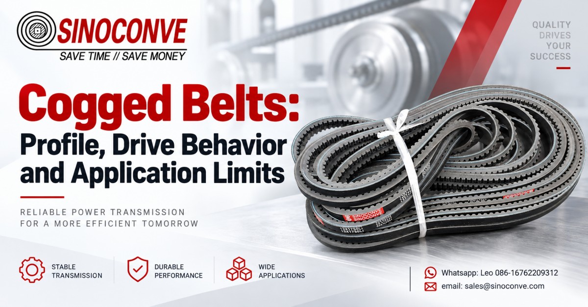
Cogged belts are usually molded or notched V-belts whose underside notches let the belt flex more easily and release heat. The cogs are relief features; they do not engage pulley teeth and do not create synchronous timing. That distinction matters at the quotation stage. A cogged V-belt transmits torque by friction on the sidewalls of a V-groove, while a timing belt transfers torque through positive tooth engagement. Calling both products “toothed belts” can send an inquiry toward the wrong profile, pulley, or length system.
We wrote this engineering entry to give maintenance teams, OEM designers, and industrial buyers a clean terminology map and a route into profile selection. It covers profile families, construction, bending behavior, thermal limits, minimum pulley logic, drive condition, failure evidence, replacement work, and order data. It does not replace a drive calculation or the dimensional table issued for a specific standard. For a project quotation, start with our industrial V-belt product range and submit the existing belt marks, sheave dimensions, speed, power, and environment together.

01Start with the Correct Belt Language
Cogged, notched, molded-notch, and raw-edge terms
Different regions use overlapping names. “Cogged V-belt” is common in North American maintenance language. “Notched V-belt” describes the visible underside geometry more literally. Metric narrow profiles are often sold under molded-notch or raw-edge cogged descriptions. A raw edge means the load-carrying sidewall is not fully enclosed by an outer fabric wrap; it does not mean that every raw-edge belt must have notches. Likewise, a molded cog does not tell us the tensile-cord material, compound, profile standard, or accepted length tolerance.
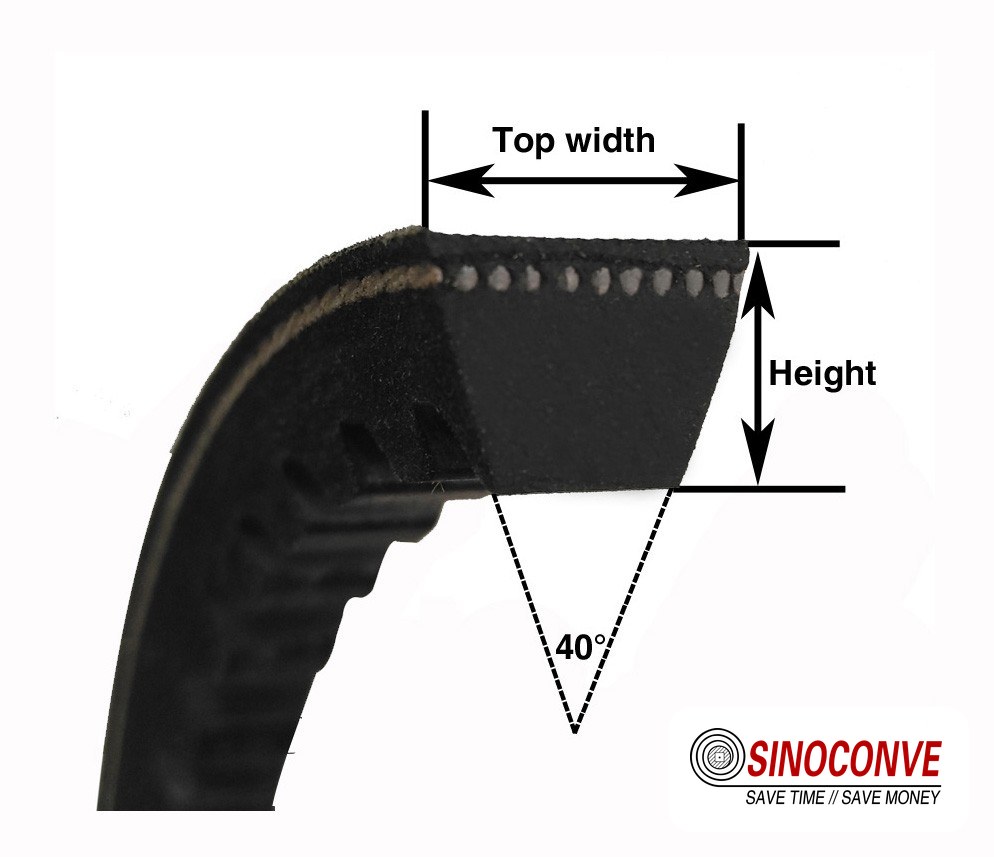
Procurement should therefore treat the name as a starting label, not a complete specification. We ask for the printed marking and a photograph of the belt cross section. If the marking is gone, measure top width, nominal height, outside circumference, and sheave groove. Record whether notches are on the inner surface only or on both inner and outer surfaces. Double-cogged constructions exist for reverse-bend paths, but their suitability depends on the specific drive and manufacturer data.
Why “toothed belt” is risky on an RFQ
A plant may call a cogged V-belt a toothed belt because it has repeated projections and valleys. That visual description is understandable, yet mechanically incomplete. Cogged belts wedge into smooth V-grooves. Timing belts mesh with a pulley that has matching tooth pitch. If exact shaft phase, index registration, or zero-slip positioning is required, the engineer normally evaluates a synchronous timing belt system, not a friction V-drive.
A toothed conveyor belt is a third category. Its top or bottom pattern may support product movement, indexing, or drive engagement, depending on construction. It should not be ordered by a V-belt code. The distinction protects the buyer from a dimensional mismatch and prevents the supplier from assuming the wrong pulley interface.
| Term on inquiry | Probable meaning | Drive interface | Evidence to request |
|---|---|---|---|
| Cogged V-belt | Notched compression section, often raw edge | Friction at V-groove sidewalls | Profile code, full mark, sheave groove photo |
| Timing belt | Pitch-defined synchronous belt | Positive tooth engagement | Pitch, tooth form, width, tooth count |
| Raw-edge belt | Unwrapped working sidewalls; may be plain or cogged | Friction at V-groove sidewalls | Underside photo and construction requirement |
| Toothed conveyor belt | Material-handling belt with patterned or driven features | Application-specific | Drawing, material, pitch, carrying function |
02Profile Families Are Engineering Coordinates
AX, BX, and CX classical cogged families
AX, BX, and CX generally identify cogged forms associated with classical A, B, and C V-belt cross sections. The letter X signals a notched construction in common catalog practice. It does not, by itself, establish length datum, cord type, compound grade, electrical behavior, or allowable temperature. Two belts carrying similar short marks can follow different length conventions if they come from different systems or markets. The safest replacement is based on the full legible mark plus dimensional and drive evidence.
As profile size increases from AX toward CX, the section becomes larger and its application range shifts. That simple statement should not be turned into a universal horsepower table. Power capacity varies with small-sheave diameter, belt speed, wrap angle, service factor, number of belts, and ambient or internal heat. Published ratings from the intended manufacturer remain the controlling source.
XPZ, XPA, XPB, and XPC metric narrow profiles
XPZ, XPA, XPB, and XPC commonly describe cogged metric narrow V-belts. Narrow-wedge geometry can support compact power transmission, but the belt and sheave must belong to compatible dimensional systems. A belt that seems close by top width may ride at the wrong radial position. It may bottom in the groove or protrude excessively. Both conditions alter effective pitch diameter and load sharing.
Our engineering review checks the complete designation, not just the profile prefix. Buyers who need a general explanation of profile codes can use the V-belt profile and selection guide. Detailed decoding belongs to the dedicated V-belt size and profile chart; this page stays focused on the engineering behavior of cogged families.
3VX and 5VX inch narrow families
3VX and 5VX are familiar narrow cogged profile families in inch-oriented markets. Their marking and length interpretation must be checked against the catalog that governs the replacement. Never assume that a numeric suffix always represents outside length, effective length, or pitch length in the same way. For a shutdown-critical drive, send the entire mark and a scale photograph before removing every old belt. A sheave-groove gauge measurement adds valuable confirmation.
| Family | Common market description | Typical RFQ risk | Confirmation route |
|---|---|---|---|
| AX / BX / CX | Classical-section cogged belts | Prefix supplied without length convention | Full belt mark and measured circumference |
| XPZ / XPA / XPB / XPC | Metric narrow cogged profiles | Mixing incompatible belt and groove standards | Profile gauge, sheave drawing, catalog datum |
| 3VX / 5VX | Inch narrow cogged profiles | Reading suffix as the wrong length basis | Manufacturer rating table and complete code |
| Double cogged variants | Notches on inner and outer surfaces | Assuming reverse bend is automatically acceptable | Drive layout, backside idler diameter, maker approval |
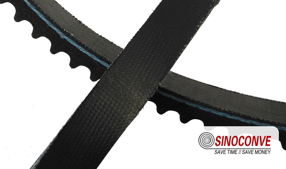
03Inside a Cogged V-Belt
Tensile cords carry the working pull
The tensile member carries most of the circumferential load. Cord material, twist, placement, adhesion, and dimensional consistency influence elongation, load sharing, fatigue resistance, and matching. The cord line also affects the belt's effective length in the drive. Bending it repeatedly around a small sheave creates cyclic strain. A notch can reduce strain in the rubber beneath the cord, but it does not remove cord fatigue or permit an unlimited reduction in pulley diameter.
Do not judge cord quality from belt color. Ask the supplier to confirm the construction appropriate to the profile and duty. Also keep oils, solvents, and aggressive cleaners away unless compatibility has been established. A swollen compound can lose support around the cord long before the belt breaks visibly.
Adhesion layer connects unlike materials
An adhesion rubber layer helps transfer shear between the tensile cord and surrounding body. It must bond materials that respond differently to temperature and strain. Poor adhesion, excessive heat, chemical exposure, or repeated overload may initiate separation. Once a localized separation grows, load distribution changes and the belt may show a bulge, split, or exposed cord.
Compression rubber and notch roots manage flex
The compression section deforms as the belt enters and leaves each sheave. Notches remove selected material from this zone so the section bends with less internal deformation. The root radius matters because a sharp corner concentrates strain. Mold consistency and compound resistance are therefore part of fatigue performance. Cracks at many notch roots can point to age, heat, an undersized sheave, excessive tension, or a compound unsuited to the environment. One symptom alone does not prove one cause.
Raw sidewalls and optional fabric treatment
Many cogged belts use precisely formed raw sidewalls to develop stable friction against the sheave groove. Some constructions include fabric treatment in selected surfaces or layers for wear control, molding, noise, or handling. “Raw edge” is not a license to run against a damaged groove. Rust, burrs, polished contamination, and incorrect groove angle can all reduce grip or abrade the sidewall.
Field note from our engineers: When a removed belt shows one glossy sidewall and one relatively matte sidewall, we inspect alignment and sheave position before debating compound grade. Unequal contact can create heat on one flank while the operator sees only “belt slip.” A straightedge, groove gauge, and clean sheave face often explain more than the belt label alone.
04How the Notches Change Bending Behavior
Reduced compression work on pulley entry
A solid compression section must squeeze and recover as it wraps around a pulley. Repeating that deformation consumes energy and generates heat through hysteresis. By removing rubber from controlled zones, the molded notches let adjacent blocks move with less resistance. This is the central mechanical reason for cogging. The sidewalls still carry frictional traction; the notch faces are not intended to mesh with the sheave.
The benefit is most relevant where flexing loss contributes materially to belt temperature or where compact geometry demands repeated curvature. Yet drive efficiency is a system result. Bearing condition, alignment, belt tension, sheave groove finish, ventilation, and load cycle can outweigh the theoretical difference between two constructions.
Notch pitch is not timing pitch
The distance between notch centers may look like a pitch, but it is not a synchronous drive pitch. Notch spacing is chosen to control flexibility and block stability within a V-belt construction. There is no matching tooth cavity in an ordinary V-sheave. A timing belt, by contrast, requires matching pulley tooth geometry and a defined pitch line. For deeper coverage of that technology, see our timing belt types and pitches guide.
Heat paths improve, but temperature still needs measurement
Notches increase exposed surface area and reduce the volume of repeatedly flexed compression rubber. Both effects can support lower operating temperature. They do not guarantee a fixed temperature reduction. A belt enclosed behind a guard with little airflow can remain hot. Slip can add heat rapidly at the sidewall, while an over-tensioned belt can heat through bending and increase bearing load.
Measure in a repeatable way. Record ambient temperature before start, then use the same instrument and location after thermal stabilization. Compare all belts in a set and both sheaves. A 10 degrees C difference between neighboring belts on the same drive is often more diagnostically useful than an isolated reading with no baseline. Follow the machine maker's safety procedure; never reach through a guard on a running drive.
05Small-Pulley Logic Has Several Limits
Minimum diameter protects more than rubber
A flexible notched section can run around smaller sheaves than a less flexible equivalent in some published rating systems. That does not mean any small diameter is acceptable. The tensile cord still bends. Centrifugal force rises with speed. Groove contact, wrap angle, and available traction remain finite. The applicable manufacturer table should define minimum recommended diameter or rating corrections for the profile, speed, and service.
We treat pulley diameter as a calculation input, not a sales adjective. Give outside diameter, pitch or datum diameter if known, groove count, groove angle, and measured top width. A photo with a ruler is useful, though it does not replace a drawing. If space constraints force a small driver, the designer may need more grooves, a different profile, a larger pulley ratio arrangement, or another transmission architecture.
Belt speed changes the stress picture
Belt speed affects power capacity, centrifugal tension, heat generation, vibration response, and service life. Low speed is not automatically easy duty because high torque can demand substantial effective tension. High speed is not automatically unacceptable because a well-designed, balanced drive may operate smoothly within published limits. State driver rpm and sheave diameter so speed can be calculated. If rpm varies, provide minimum, normal, and maximum values rather than one nominal point.
Wrap angle and idler position alter loading
Small wrap angle reduces the available frictional contact on the smaller sheave. An idler may increase wrap, tension the belt, or clear an obstruction, but its side, diameter, and position change belt flexing. A backside idler produces reverse bending and needs specific approval. An inside idler should match the belt interface and avoid forcing the belt too deeply. Include idlers on the RFQ sketch. Omitting them can invalidate a seemingly correct profile recommendation.
SINOCONVE is a Ningbo, China factory producing conveyor and transmission products with in-house molding, vulcanizing, inspection, and jointing capability. For the cogged-belt route, our V-belt product hub is the primary engineering entry. Buyers with broader plant packages may also coordinate with a transmission belt manufacturer while sourcing adjacent conveying items from a qualified conveyor belt manufacturer.
06Tension, Alignment, and Sheave Condition
Use a measured installation target
Installation tension must be high enough to transmit load without damaging slip, but not so high that it overloads cords, shafts, and bearings. Thumb deflection is inconsistent because hand force, span, profile, and access differ. Use the machine or belt supplier's force-deflection method, sonic-frequency method, or specified tensioning procedure. Record span length and measurement conditions. Recheck after the prescribed run-in period because seating can change the reading.
A slipping drive sometimes receives more tension as a quick response. That may hide a worn sheave for a short time while bearing load rises. Look for polished groove surfaces, corrosion, debris, wall wear, incorrect groove depth, and contamination first. If the belt bottoms, extra force cannot restore proper sidewall wedging. Replace or re-machine the sheave according to approved practice rather than using belt tension as compensation.
Alignment needs angular and offset checks
Angular misalignment points the shafts in different directions. Offset misalignment leaves parallel shafts but places the sheaves in different planes. Both can drive the belt toward one groove wall, creating uneven wear and heat. A straightedge is a practical first check for accessible sheaves; a suitable laser tool can improve repeatability on longer spans. Verify shaft and bearing condition before moving a sheave, because runout can imitate a static alignment problem.
Groove wear changes the effective drive
A V-belt should transmit through sidewall contact. Wear widens the groove and lets the belt ride lower. Severe wear allows bottom contact, reduces wedge action, and changes effective diameter. This can disturb speed ratio and matching across a multi-groove drive. A groove gauge gives a faster, more reliable assessment than visual judgment alone. Check every groove; one damaged groove can overload the neighboring belts.
| Inspection item | Useful evidence | Risk if ignored | Action before restart |
|---|---|---|---|
| Installation tension | Force-deflection or frequency reading | Slip, overload, heat, bearing damage | Adjust to approved target and document |
| Sheave alignment | Straightedge or laser reading at multiple positions | One-sided wear and belt rollover | Correct offset and angular error |
| Groove condition | Gauge contact, wall finish, debris check | Bottoming or reduced traction | Clean or replace worn sheave |
| Runout and bearings | Indicator reading, noise, vibration, play | Cyclic tension and edge damage | Repair mechanical source before belting |
07Matched Sets and Banded Arrangements
Multi-groove drives need shared load
Belts running side by side should have compatible effective lengths so each one carries a reasonable share. A loose member contributes little torque and may flap; a tight member carries excessive load and heats. Never mix a new belt with several worn belts on a critical set. Their cross sections, effective lengths, and stiffness histories differ. Replace the complete set, then store the removed samples long enough to support root-cause review.
Ask for matched-set supply when the drive requires it. Keep all set labels together during receiving and installation. Do not combine belts merely because the nominal printed code is identical. Confirm the supplier's matching method and tolerance system. For an existing machine, count grooves and report whether every groove is occupied.
Banded variants address lateral behavior
A banded assembly connects multiple V-sections with a common top band. It can stabilize belts under pulsating loads, shock, or conditions where individual sections tend to whip or turn over. The band adds construction constraints and requires compatible sheaves. Debris accumulation, groove mismatch, and sheave alignment remain important. A banded product should not be installed as an improvised substitute for separate belts without checking dimensions and ratings.
For the selection boundaries and drive geometry that belong to this architecture, consult the banded V-belt drive system guide. This article only locates banded cogged options within the wider taxonomy.
Pulsating torque requires system evidence
Reciprocating compressors, crushers, and some agricultural machines impose torque fluctuations that differ from a steady fan load. State the driven machine, starting method, starts per hour, peak load behavior, and any flywheel. Service factor is not a universal number that can be guessed from motor kilowatts. The duty cycle determines how often cords, sidewalls, and tensioning hardware experience peak stress.
Field note from our engineers: On multi-groove inspections, we mark each belt position before removal and lay the set in order. A belt with deeper sidewall polish beside a cleaner neighbor often reveals a groove or matching issue. Mixing the pile erases that evidence in seconds.
08Application Boundaries and Environmental Inputs
Temperature is local, dynamic, and compound-dependent
Ambient air temperature is only one value. The belt sees bending heat, sidewall friction, radiant heat, restricted airflow, and conducted heat through shafts or sheaves. A drive beside an oven may have a cool morning reading and a much higher stabilized afternoon temperature. Record the normal and peak ambient values, exposure duration, enclosure condition, and measured belt or sheave temperature if safe procedures allow.
Temperature limits depend on the exact compound and construction. Do not transfer a limit from one catalog to an unverified replacement. If a high-temperature environment also contains oil mist or ozone, state all exposures because combined aging can differ from a single laboratory condition.
Oil, dust, water, and chemicals change traction
Oil can soften or swell an incompatible elastomer, reducing dimensional stability and adhesion. Fine dust may polish, abrade, or pack into guards and sheaves. Water can temporarily alter friction and carry contamination into the groove. Cleaning chemicals create another compatibility question. The inquiry should name the substance, concentration where known, contact mode, frequency, and cleaning process.
A belt guard protects personnel and helps control debris, yet a sealed guard can restrict cooling. Maintenance should assess both functions. Never remove a required guard as a thermal fix. Improve ventilation only through an approved machine-safety review.
Speed ratio accuracy has a practical limit
Cogged V-belts are friction belts. Creep and occasional slip mean they do not provide the exact phase relationship of a synchronous drive. They work well in many fans, pumps, compressors, agricultural machines, and general industrial transmissions where controlled friction is acceptable. They are not the correct architecture when the driven shaft must maintain exact angular registration for every cycle. The dedicated V-belt versus timing belt guide owns that system-level choice.
Conveyor operations may need both drive and carrying belts
A plant procurement package can include cogged transmission belts and conveying belts, but their specifications must remain separate. For bulk-material duty, an industrial conveyor belt is defined by carcass, covers, width, strength, and service conditions rather than a V-profile. An EPC buyer may request an rubber conveyor belt and cogged drive belts on one schedule, while a conveyor belt supplier handles the material-carrying specification.
Distribution projects sometimes combine power-transmission spares with wholesale conveyor belts. A regional conveyor belt distributor should preserve separate item masters, and a visit to our conveyor belt factory information helps teams understand the wider manufacturing scope. For V-drive inquiries, work directly with a qualified V-belt manufacturer.
09Read Failure Evidence Before Disposal
Cracks at notch roots
Small root cracks distributed across the belt can develop through flex fatigue, thermal aging, ozone exposure, excessive tension, or operation below the recommended sheave diameter. Their depth, distribution, and age matter. Photograph a cleaned section at close range and another view showing the full belt. Record service hours if available, but do not estimate them as fact when no log exists.
One deep localized crack suggests a different path from uniform shallow checking. Inspect for trapped debris, an impact, installation damage, or a damaged sheave region. If cords are visible, remove the belt from service under the site's maintenance rules. Continuing operation risks separation and secondary machine damage.
Glazing and hardened sidewalls
A shiny sidewall commonly accompanies slip or prolonged frictional heating, although contamination can also create a glossy surface. Check tension, load, groove wear, and startup behavior. A belt may squeal only during acceleration, so a no-load observation can miss the event. Hardened rubber with surface checking often indicates thermal or age-related deterioration. Do not dress the belt with sticky compounds; they can mask the cause and contaminate sheaves.
Cord exposure, edge fray, and separation
Exposed tensile cord is a serious condition. Possible contributors include severe sidewall wear, misalignment, prying during installation, foreign-object contact, or internal adhesion failure. Edge fray concentrated on one side makes alignment and flange or guard contact especially important. A swelling or blister should trigger a compound and heat review as well as inspection for separation.
Bottoming, rollover, and thrown belts
Bottoming leaves evidence at the belt's narrow inner region and often accompanies worn or incompatible grooves. Rollover can arise from low tension, shock load, misalignment, inadequate lateral stability, worn sheaves, or an unsuitable profile. A thrown belt may be the final event rather than the first cause. Inspect guards, shaft movement, tensioning travel, sheave retention, and foreign material before installing a replacement.
| Observed symptom | Possible contributors | Check next | Do not assume |
|---|---|---|---|
| Notch-root cracking | Heat, age, tight bend, excess tension, ozone | Diameter, temperature log, tension record | That notches themselves caused failure |
| Glazed sidewalls | Slip, overload, worn groove, contamination | Startup load, groove gauge, belt tension | That more tension is always the cure |
| Cord exposure | Abrasion, prying, misalignment, separation | Installation method and contact points | That remaining belts are undamaged |
| Belt rides low | Worn groove or wrong profile | Groove dimensions and belt cross section | That nominal length caused bottoming |
| Rollover | Shock, alignment, low tension, groove wear | Drive motion under safe observation | That a wider belt will fit the sheave |
| Unequal set wear | Mismatching, groove variation, runout | Each belt and each groove by position | That one replacement belt will share load |
For a broader causal workflow beyond this taxonomy, use our V-belt failure modes and field fixes. It helps maintenance teams separate symptom, mechanism, and corrective action rather than ordering the same part into the same fault.
10Replacement Workflow for a Controlled Restart
Lock out, preserve evidence, and clean dry
Follow the site's isolation and verification procedure before opening the guard. Photograph the installed drive from several angles. Mark belt positions in a multi-groove set and copy every readable character. Note debris, odor, rubber dust, oil, and any abnormal guard contact. Remove tension through the designed adjustment; never force a belt over a sheave with a screwdriver. Prying can cut cords and damage the groove.
Clean the sheaves with a method approved for the machine and belt materials. Keep residue-producing dressings away. Turn shafts only under the authorized procedure and inspect the full circumference. Check retention, keys, bushings, and fasteners according to machine documentation. If the sheave is cracked or visibly damaged, replacement takes priority over a new belt installation.
Verify geometry before fitting new belts
Measure groove condition, alignment, center distance, tensioning travel, and runout where appropriate. Confirm the new profile seats on its sidewalls without bottom contact. Compare the new set markings and matching identification. A correct belt should install without violent force when center distance or tensioning hardware is properly released. If it will not, stop and recheck the designation and machine adjustment.
Tension, rotate, guard, and observe
Apply the specified initial tension using a calibrated or approved method. Rotate the system by hand only where the lockout procedure permits, allowing belts to seat while watching for interference. Recheck alignment and tension. Refit all guards before powered testing. At restart, observe from the designated safe position for abnormal noise, vibration, odor, or movement.
Take a baseline temperature after the drive reaches a stable operating state. Record load and ambient conditions so the number can be compared later. Follow the stated run-in and re-tension schedule. A short inspection after commissioning often catches loose hardware, uneven seating, or a tension change before it develops into visible belt damage.
Field note from our engineers: We do not throw the old set away until the replacement drive has completed its controlled restart. The old marks can resolve a length question, and the wear pattern can expose the source of a temperature rise. Once those belts enter a mixed scrap bin, the evidence is usually unrecoverable.
11Build an RFQ That an Engineer Can Rate
Start with identity and geometry
Send the full belt marking exactly as printed, including spaces, prefixes, suffixes, and brand references visible on the old part. State quantity per drive and number of identical drives. Provide top width and height measurements when the code is incomplete. Add inside, outside, or effective circumference only if the method is known; name that method rather than writing “length.” Photographs should show the mark, cross section, notch pattern, and installed sheaves.
Add power, speed, and service data
Motor nameplate power alone is not enough. Include driver type, driver rpm, driven rpm or desired ratio, both sheave diameters, groove count, center distance, wrap arrangement, idlers, operating hours per day, starts per hour, starting method, and load character. Identify shock or pulsation. If a variable-frequency drive changes motor speed, state the operating range and time spent near each condition.
The machine function gives context. A ventilation fan, slurry pump, reciprocating compressor, grain elevator, and crusher can present very different start and load patterns at the same nominal kilowatts. State whether a jam or stall can occur. Describe any torque limiter or clutch.
Describe environment and acceptance needs
List ambient minimum and maximum temperature, nearby heat sources, oil type, water, dust, ozone, outdoor exposure, chemicals, and cleaning agents. State whether the drive is enclosed and how it is ventilated. For regulated equipment, identify the applicable market and machine standard rather than assuming a generic “industrial grade” covers it.
Commercial fields still matter: destination, annual forecast, required packaging, private label needs, sample quantity, and requested documentation. Lead time, minimum order quantity, and warranty can only be confirmed against actual profile, quantity, drawings, and operating conditions. Our team will not turn an industry-typical range into a project promise without reviewing those inputs.
| RFQ field | Preferred detail | Why it affects selection |
|---|---|---|
| Existing marking | Complete code and clear photo | Identifies profile and likely length convention |
| Cross section | Top width, height, notch arrangement | Checks family when printing is missing |
| Sheaves | Diameters, grooves, groove gauge, condition | Controls bend, speed, seating, and capacity |
| Drive rating | Power, rpm range, ratio, starts per hour | Defines load and cyclic demand |
| Layout | Center distance, wrap, idler side and diameter | Reveals reverse bends and contact limits |
| Duty | Machine type, hours, shock, stall possibility | Supports service-factor review |
| Environment | Temperature, oil, water, dust, chemicals | Influences compound and aging risk |
| Supply format | Single, matched set, or banded assembly | Determines load sharing and packaging |
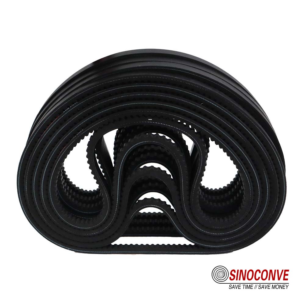
12A Practical Engineering Route from Name to Approved Part
Gate one: establish belt category
First decide whether the existing mechanism is a friction V-drive, a synchronous tooth drive, or a conveying system. Look at the pulley. Smooth angled grooves indicate a V-belt interface; pitch-shaped teeth indicate synchronous engagement. This one observation prevents the most expensive naming error. Then identify whether the V-belt is plain, notched, double cogged, individual, or banded without turning that observation into an automatic product choice.
Gate two: establish dimensional family
Use the full code, cross-section measurements, and sheave geometry to locate the family: AX/BX/CX, XPZ/XPA/XPB/XPC, 3VX/5VX, or another documented profile. Confirm the governing length convention from manufacturer data. Do not convert between systems by comparing only nominal top width. Do not shorten a code during purchasing-system entry if the omitted suffix carries construction or length meaning.
Gate three: validate drive limits
Check power, speed, small-sheave diameter, wrap, center distance, number of belts, service, starts, shock, reverse bends, tensioning range, temperature, and contaminants against the intended rating method. This is where the notch's flexibility becomes one input among many. If any input falls outside a published boundary, ask for an engineered review instead of applying a general catalog statement.
Gate four: close the maintenance loop
Correct alignment and sheave condition, fit a complete matched set where required, tension by an approved method, guard the drive, observe restart, and document the baseline. Keep failed-belt evidence. The purchasing record should connect the final approved part to the machine asset, drive geometry, and service conditions. That record makes the next replacement faster and reduces dependence on a fading ink mark.
For broader maintenance context, our transmission belt selection and maintenance guide covers the surrounding practices. To explore the specific sourcing distinctions already addressed elsewhere, use the classic and cogged V-belt comparison, the cogged manufacturer and wrapped supplier comparison, and the focused raw-edge cogged V-belt selection article. Those pages own those decisions; the present page remains the terminology and engineering entrance.
13Procurement Controls for Consistent Supply
Approve a drawing or controlled specification
A short catalog code is convenient, but a controlled purchasing specification is safer. It can state profile family, applicable dimensional reference, length designation, construction category, matched-set requirement, marking, packaging, and the application inputs used for approval. If substitutions are allowed, define who reviews them. Avoid an open phrase such as “or equivalent” when pulley compatibility and length datum have not been documented.
Inspect incoming goods without destructive assumptions
Receiving inspection can verify labels, quantity, visible dimensions, matching identification, surface condition, date or batch traceability where supplied, and packaging integrity. Store belts away from direct sunlight, ozone-producing equipment, heat, chemicals, and deformation. Do not hang a belt from a narrow hook for months. Rotate stock under the facility's shelf-life policy and keep matched sets together.
Use samples to close specification gaps
When the old code is obsolete or ambiguous, send an unused reference if available and a representative failed belt with position notes. A sample helps confirm geometry but does not reveal every original material property. Pair it with duty data. For an OEM development, a drawing and drive calculation are better than reverse engineering a belt that has stretched, worn, and heated in service.
We can review cogged belt inquiries alongside V-belts and synchronous belts from our transmission range. Give us evidence, not only a nickname. That is the shortest route to a technically defensible quotation and a stable replacement record.

14Frequently Asked Questions About Cogged Belts
Do the cogs on a cogged V-belt engage the pulley?
No. The belt transmits power through friction at its angled sidewalls against a V-groove. The underside notches help the section flex and manage heat; they are not synchronous teeth.
Is a cogged belt the same as a timing belt?
They are different transmission principles. A timing belt uses teeth that mesh with a matching pulley and preserve angular relationship. A cogged V-belt can experience creep or slip because it is a friction drive, even though its underside looks tooth-like.
What do AX, BX, and CX mean?
They commonly identify cogged versions associated with classical A, B, and C cross-section families. The X points to a notched construction in common naming. Exact dimensions and length interpretation still require the applicable standard or manufacturer catalog.
What do XPZ, XPA, XPB, and XPC identify?
These are commonly used metric narrow cogged profile families. They are not interchangeable merely because two belts look close in width. Confirm the sheave groove, full code, and length convention.
Can I use a smaller pulley because the belt is cogged?
Only within the published limits for the exact profile and operating conditions. Notches improve flexibility, but tensile-cord fatigue, belt speed, wrap, heat, and power rating still impose boundaries. Submit the small-sheave diameter and rpm for review.
Should I replace only the failed belt in a multi-belt drive?
Usually, replace the full matched set when the drive is designed for matched belts. A new belt mixed with worn units can carry a disproportionate load. Inspect all grooves and determine why one member failed first.
Why are cracks forming at the notch roots?
Heat, aging, excessive tension, a pulley below the recommended diameter, ozone, and repeated flex fatigue are possible contributors. Look at crack depth and distribution, then review measured temperature, sheave size, alignment, and tension history. One photograph is useful, but a diagnosis needs the drive data too.
Does a cogged belt always run cooler?
Not always. Its geometry can reduce bending loss and expose more surface, yet slip, poor airflow, excess tension, a worn groove, or overload can still make it hot. Compare repeatable temperature readings under known load and ambient conditions.
Can belt dressing solve squeal or slip?
Do not use dressing as a substitute for diagnosis. It can contaminate surfaces and conceal worn grooves, incorrect tension, overload, or alignment errors. Clean and inspect the drive using approved procedures, then correct the mechanical cause.
What information should accompany a cogged-belt RFQ?
Send the full marking, profile dimensions, quantity and set arrangement, sheave diameters and grooves, rpm, power, center distance, idlers, operating hours, starts, load type, temperature, contaminants, and photographs. If a standard or machine drawing controls the part, attach it. State whether the recorded length is inside, outside, effective, or unknown.
15Related Products You May Need
- V-belts for industrial power transmission — the main product route for profile confirmation and quotations.
- Timing belts — for drives that require positive tooth engagement and controlled shaft phase.
- Rubber conveyor belts — heavy-duty material-carrying products for mining, quarrying, cement, and port systems.
- EP rubber conveyor belts — fabric-carcass conveying options for varied industrial duties.
16Related Blog Posts
- V-Belt Ultimate Guide: Profiles, Sizes, and How to Choose
- V-Belt Failure Modes, Root Causes, and Field Fixes
- Banded V-Belt Drive System Selection
- Transmission Belt Guide: Choosing and Maintaining a V-Belt
- Classic V-Belts and Cogged V-Belts: Dedicated Comparison
- Raw-Edge Cogged V-Belt Selection for Industrial Drives