
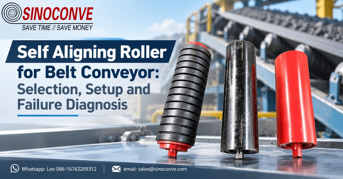
A self aligning roller for a belt conveyor only earns its cost when the belt is already tracking inside a range the roller can influence. Treat it as one component of a tracking system instead of a cure for a crooked machine, and the whole selection problem becomes far clearer. This guide follows that logic, from choosing the right form, through placing it along the line, to reading the failure symptoms that send crews back to the stores.
Twenty years of field reports taught us an uncomfortable lesson. Most "the training roller failed" complaints we receive are not roller failures at all. They are structural faults — a skewed idler set, an off-centre loading point, head and tail pulleys that are not parallel — that no training roller can correct, because the roller treats the symptom while the cause keeps pushing the belt sideways. Repair the geometry first. Then buy the roller.

01What a Training Roller Can and Cannot Do
A training roller generates a small lateral force when the belt drifts off centre, then removes that force once the belt comes back. Nothing more elaborate than that. It sits in the carrying run or the return run, senses the belt edge through its own geometry, and converts that offset into a steering moment. On a 1,200 mm belt travelling at 3.0 m/s, the correction it can apply is measured in a few hundred newtons, not in tonnes.
That ceiling shapes the whole specification. A unit built for 800 mm belt width will never steer a 1,400 mm belt, however many of them you bolt to the frame, because the moment arm and the contact geometry are simply too small. Belt width, belt speed and the mass being carried together set the correcting force you need, and we work those numbers through later in this article.
Where the roller helps, and where it merely hides a fault
Training rollers earn their place where the drift is gradual and repeatable, such as a belt that creeps 40 mm to one side over a 200 m run and returns as soon as the load lightens. They also help where the belt is slightly off-square after a splice, since the roller can bias the run until the joint settles. What they cannot do is beat a frame that pushes the belt sideways by design.
We have watched crews add a fourth and then a fifth training roller to a single transfer point while a crooked chute kept throwing material onto the left third of the belt. Each new roller bought a few days of calm, and then the drift returned exactly as before. The correct repair was a chute adjustment worth two hours of work, and it held for several years. Reach for the roller after the structure is square.
02Read the Drift as a Number Before You Buy Anything
Before a single roller is ordered, measure the fault. A tracking problem is a number, not an impression, and the toolkit is cheap: a steel tape, a plumb line, a laser pointer on a tripod, and a chalk mark on the belt edge. Record the belt edge position at three points — just after the loading point, near mid-run, and approaching the head pulley — then repeat the whole set with the belt empty and again with it loaded.
Those six readings separate the mechanisms. A belt that runs true empty and drifts only when loaded points at the loading point, and a training roller will simply fight the stream. Drift that is identical loaded and empty sends you to idler square and pulley alignment first. Drift that changes direction from one pass to the next points at the belt body itself, or at a splice that was cut off-square.
Measuring drift in millimetres, not in impressions
Fix the belt edge reference to a frame member once and reuse the same mark on every visit. Using a fresh datum each time is how two engineers end up describing one conveyor in two different ways. On a 1,000 mm belt, a 25 mm shift between the empty reading and the loaded reading marks the line between a nuisance and a genuine tracking fault that will polish the edge within a season.
Our own field rule is blunt. Under 15 mm of drift, watch it. Between 15 and 40 mm, square the structure and add a single training roller. Above 40 mm, stop buying hardware until the cause is found, because at that level something is actively steering the belt. This is also the boundary where a conveyor belt manufacturer can only advise rather than supply, since neither belt nor roller outruns a frame that pushes sideways by design.
03Friction, Tapered and Pivoted: Matching the Form to the Duty
Three families of training roller dominate bulk handling, and each steers the belt by a different mechanism. Choosing the wrong family is the most common specification error we meet on site, and it usually appears as a roller that turns freely but never corrects anything. We set the three side by side below, using the values that appear on most of our project drawings.
| Form of training roller being compared | How this form produces its correcting force | Duties where this form earns its place | Where this form falls short in service |
|---|---|---|---|
| Friction type with angled side rollers | Angled side rollers touch the belt only after it has already drifted off centre | Belts below 1,000 mm running under about 2.5 m/s where the correction can be gentle | At high speed the belt lifts clear of the side rollers and the unit sits idle |
| Tapered or conical end rollers | Conical ends spin at different surface speeds and drag the belt back toward the centre line | Faster lines and reversing conveyors when the set is built symmetrically end to end | Cone faces wear quickly on sharp abrasive material unless the cover compound is harder |
| Pivoted or hinged roller set | The whole set rotates about a central spindle and steers through that turning motion | Wide heavy lines with 1,400 to 2,000 mm belts that need the strongest available force | A seized pivot turns the strongest unit into a fixed obstruction across the belt path |
Friction and self-centring side rollers
The friction form relies on angled side rollers that touch the belt only after it has already drifted. Contact distance is short, so the correction stays gentle and the unit is inexpensive to rebuild when a roller finally wears out. On belts under 1,000 mm running below 2.5 m/s, this is often the right first choice. Push the same unit onto a 1,400 mm line at 4 m/s, though, and the belt lifts off the side rollers on every troughing pass, leaving the assembly idle while the drift grows.
Tapered or conical end rollers
A tapered roller carries conical end sections that spin faster at the large diameter and slower at the small one. That speed difference drags the belt back toward the centre without needing the belt to touch an extra part, which is why the design tolerates more speed than the friction form. Built symmetrically, it also works on reversing conveyors. Wear concentrates on the cone face, so an abrasive duty calls for a harder cover compound and a roller selection guide worth reading before the order is placed.
Pivoted (hinged) roller sets
The pivoted, or hinged, set rotates about a central vertical spindle. Belt friction against the angled rollers turns the whole set, and that turning motion steers the belt home again. Correcting force is the highest of the three forms, which is why wide, heavy lines with 1,400 to 2,000 mm belts usually specify it. The price is a pivot that has to stay free; a seized spindle converts the strongest training roller into a fixed obstruction lying across the belt.
04Belt Width, Belt Speed and Load Set the Size You Need
Three variables decide how much correcting force a line actually requires, and they interact. Wider belts carry more of the load off centre, so a 1,400 mm belt needs a roughly 40 percent larger correction than a 1,000 mm belt at the same drift. Faster belts spend less time in contact with the correcting surface, so a 4 m/s line reacts more slowly than a 2 m/s one. Heavier material raises the transverse push the roller has to overcome.
There is a practical way to think about it without a full dynamics study. The correcting force a training roller can develop scales with the contact load on it, and the contact load scales with belt width and trough fill. Double the belt width and you roughly double both the available force and the force required, which is why width alone rarely changes the answer. What does change the answer is load distribution: a belt loaded on one side needs far more correction than one loaded centrally.
Why belt speed changes the reaction, not the force
Speed is the variable crews most often forget. A training roller senses drift through the belt edge and responds over a distance, so a line running at 4 m/s covers that distance in half the time of a 2 m/s line. The force available is similar, but the belt has less opportunity to settle between troughing sets. On high-speed lines we therefore shorten the spacing between training units rather than fitting a heavier single unit, and we keep the return-side unit close behind the first carrying-side one.
Every serious conveyor belt supplier will tell you the same thing about load: it is rarely uniform. A stone line fed from a crusher discharge drops material in a heap that is heavy on the drive side, and that heap steers the belt long before the roller does. Measure the load profile at the loading point once, and you will usually find the drift origin within a metre of it.
05What a Reversing Conveyor Demands of a Training Roller
A conveyor that runs in both directions doubles the difficulty of tracking. A one-way belt that drifts is corrected in one direction of travel, and the roller only ever has to work one way. Reverse the belt and the same roller now sees the drift from the other side, so a unit set for forward running can actually worsen the fault when the belt runs backward. This is the single most quoted complaint we receive about training rollers on shuttle and tripper lines.
The remedy is symmetry, and it starts at the specification stage. Any roller used on a reversible line has to be geometrically symmetric about its centre, so the correcting force it develops is the same in both directions of travel. Asymmetric friction units, which work well on one-way lines, have no place on a reversing conveyor, no matter how cheap they are.
Symmetric geometry is not optional on reversible belts
We specify symmetric tapered or pivoted sets for every reversible duty, and we pair them so that the lead and lag angles mirror each other about the centre. On a 1,200 mm shuttle conveyor serving a stockpile, a correctly mirrored pair held the belt within 20 mm in both directions, while a single asymmetric unit on a sister line drifted 70 mm one way and 55 mm the other. The belt, grade and tension were identical; only the roller layout differed.
One more consequence deserves attention. Reversible conveyors usually switch direction with the belt partly loaded, and a partly loaded belt has a different centre of gravity than an empty one. A industrial conveyor belt carrying a leaning load will pull toward the heavy side for the first few metres after every direction change, so the first training unit should sit close behind the drive on each end.
06Position Along the Line: How Far from the Drive
The first training roller on the carrying side belongs a set distance from the drive pulley, not immediately against it and not so far away that the drift has already grown. We place the first carrying-side unit 8 to 12 belt widths from the head pulley on a normal line, and the first return-side unit 6 to 8 widths back from the tail. On a 1,000 mm belt that works out to roughly 8 to 12 m from the head.
Getting closer than that is a common mistake. A training roller sitting within one or two metres of the drive sees the belt at its highest tension, where the belt is least willing to move sideways, so it does almost nothing. Moving it too far the other way means the belt arrives already 60 mm off centre and the roller has to fight drift that has built up over the whole run. The window between the two is wider than most crews expect, and it is worth marking on the frame.
On lines where a transmission belt manufacturer also supplies the auxiliary drives, we sometimes see the training layout sketched on the same drawing as the drive package. That is a good habit. The two interact, because a drive that pulls more on one side introduces a tracking bias that the roller then has to absorb, and spacing is the cheapest way to compensate for it.
07Distance from the Loading Point and Spacing Rules of Thumb
The loading point is where most tracking faults are born, so the second training roller usually goes just downstream of it. We set that unit 3 to 5 belt widths past the skirtboard exit, by which point the material has settled and the belt has had a chance to react to the stream. Placing a training roller directly under the loading chute is wasted effort, because the skirtboard, not the roller, controls the belt there.
Beyond those two anchor positions, the mid-run spacing follows a simple pattern. Short lines under 50 m need one carrying-side and one return-side unit. Lines between 50 and 200 m take a pair every 40 to 60 m. Long overland lines take a pair every 80 to 100 m and an extra unit before any curve or transition. The table below collects the values we quote most often, expressed as multiples of belt width.
| Position on the conveyor line | Typical distance we quote in belt widths | Why this position is chosen in practice |
|---|---|---|
| First carrying-side unit behind the head pulley | Roughly 8 to 12 belt widths back from the drive | Belt tension drops enough here for the roller to actually move the belt sideways |
| First return-side unit ahead of the tail pulley | About 6 to 8 belt widths forward of the tail | Catches return-side drift before it reaches the tail and cocks the whole belt body |
| Downstream of the loading point | Roughly 3 to 5 belt widths past the skirtboard exit | By this point the load has settled and the belt can respond to a correction |
| Regular mid-run pairs on a long line | A pair every 40 to 60 m, stretched on overland runs | Keeps drift from accumulating between correction points over long spans |
How to turn the rules of thumb into a real layout
Rules of thumb get you a first sketch, nothing more. Walk the line with a tape, mark the two anchor positions, then space the remaining pairs so that no two training units sit within three belt widths of each other. Crowding them wastes money and can set up a see-saw, where one roller pushes left and the next pushes right. If you buy wholesale conveyor belts and rollers as one package, hand the supplier your measured drift figures rather than only a belt width, and the layout advice you get back will be far more useful.
08Lead and Lag Tilt Angle in Plain Numbers
Lead and lag angles are the small forward or backward tilts built into a training roller set, and they do the coarse steering before the unit has to react. A lead angle points the roller slightly toward the direction of belt travel, which nudges the belt away from that side. A lag angle, tilted the other way, does the opposite. The effect is subtle at small angles and unhelpful at large ones.
Our working range is 1 to 3 degrees of tilt, measured from square to the belt centre line. Below 1 degree you can barely measure the effect. Above 3 degrees the roller starts to act like a plough, scrubbing the belt and generating the very edge wear you were trying to prevent. On a 1,000 mm wide belt, 2 degrees of tilt moves the outer edge about 35 mm out of line, which is enough to steer without scrubbing.
Direction of tilt has to match direction of travel, and this is where reversible lines trip people up. On a one-way conveyor, lead angles are set once and forgotten. On a reversing conveyor, the tilt that works forward is the wrong tilt backward, which is why symmetric sets with mirrored pairs are the only sensible choice. A conveyor belt distributor who understands this will ask about direction changes before quoting the roller, and you should be wary of one who does not.
09Matching the Training Set to the Idler Trough Angle
A training roller only steers the belt if the belt is sitting in the trough the way the neighbouring idlers expect. If the training set carries a different trough angle than the idlers either side of it, the belt has to climb or drop as it passes, and that transition creates a local drift that cancels the correction you paid for. Match the trough angle of the training set to the rest of the run, and match the roller diameter too.
We see this most often where a plant has standardised on 35 degree troughs but a store room holds surplus 20 degree training sets from an older project. Fitting one of those into a 35 degree run makes the belt run on the inner edge of the training rollers and gives up roughly half the available correction. The fix costs nothing but a correct part number, and a conveyor belt factory worth its salt will flag the mismatch at quotation stage rather than watch you discover it on commissioning day.
Trough angle also has to suit the material. Fine dry sand under a steep trough simply runs to the centre and rides there, so the belt never develops enough edge pressure to be corrected. Coarse rock in a shallow trough spills toward the edges and pushes the belt out. Pick the trough that keeps the load in the middle, and the training roller has far less work to do.
Field note from our engineers: on a 1,000 mm aggregate line we found a training set carrying a 20 degree trough sitting among 35 degree idlers.The belt climbed onto the inner roller edge on every pass, and the plant had already replaced the unit twice. Matching the trough angle and the roller diameter removed the drift in a single afternoon.
10Symmetric Layout for Bi-Directional and Shuttle Conveyors
Bi-directional conveyors need the whole training arrangement mirrored about the line centre, not just the roller form. That means the same number of units each side of the mid-point, the same tilt angle with opposite sign, and the same trough angle throughout. Miss any one of the three and the belt will track well in one direction and walk off in the other, which is exactly the complaint that brings most reversing lines to us in the first place.
The mirror has to hold on the return side too, and that is where many designs quietly fail. Crews remember to double up the carrying-side units and forget the return side, so the empty return run tracks true when the belt moves forward and drifts badly when it moves backward. On a shuttle conveyor working a 90 m stockpile, we rebuilt a return-side layout with two mirrored units and cut the peak drift from 80 mm to under 25 mm in both directions.
One field detail is easy to overlook. A reversing conveyor usually changes direction at a fixed point, so the belt passes the same idlers twice under different tension. Training units near the drive see high tension and respond slowly; units near the tail see low tension and respond fast. Mirroring the layout keeps that imbalance tolerable, but it does not remove it, so expect a well-designed reversing line to be slightly less forgiving than a simple one-way line.
11A Worked Sizing Example for a 1,200 mm Quarry Line
Numbers make selection concrete, so here is a worked example drawn from a limestone duty we quoted recently. The belt is 1,200 mm wide, the line runs at 3.2 m/s, the throughput is 900 t/h of crushed stone, and the measured peak drift under load is 55 mm to the drive side. Our task is to estimate the correcting force required and the number of training units that will deliver it.
Step one: estimate the lateral force the drift represents
A rough but workable method is to relate the drift to the transverse load component. For a troughed belt, we use a coefficient of about 0.02 times the vertical load on the affected section to represent the sideways push from a biased load. The load per metre of belt at 900 t/h and 3.2 m/s works out to roughly 78 kg per metre. Over a 12 m correction span that is about 940 kg, and 0.02 of that gives a lateral force near 184 N that the roller has to counter.
Step two: convert force into the number of units
A single 1,200 mm pivoted training set in good condition develops a correcting force of roughly 120 to 150 N at 3 m/s, depending on trough fill. Dividing the 184 N required by 130 N available gives about 1.4, so one unit is not quite enough on paper. Two units spaced 12 m apart cover the 184 N with margin for the load bias we cannot see, which is why we specify a pair for this duty rather than a single heavier unit.
| Input in the working example | Value used in the calculation | Result this input produces |
|---|---|---|
| Belt width and running speed of the line | 1,200 mm wide and travelling at 3.2 m/s | Sets the load per metre at about 78 kg on the belt |
| Throughput and drift measured under load | 900 t/h with a peak drift of 55 mm toward the drive | Gives a lateral force of roughly 184 N to be counteracted |
| Force available from one pivoted set | About 120 to 150 N at this speed with a full trough | One unit falls short, so the duty needs two spaced units |
| Spacing selected for the correction pair | A 12 m gap between the two training units | Covers the load bias with margin and avoids a see-saw effect |
Step three: sanity-check the result against field evidence
Numbers on paper need a reality check, so we compare them with what similar lines actually do. A 1,200 mm limestone line moving 900 t/h normally runs with one carrying-side pair and one return-side unit, and that matches our two-unit result once the return side is counted. If the calculation had demanded five units on a 120 m line, we would treat that as a signal that the fault is structural rather than a shortage of rollers, and go looking for a crooked idler set or a skewed loading chute instead.
Field note from our engineers: the same 1,200 mm line was fitted with a single oversized training unit before we quoted it. That unit corrected the light load but not the 900 t/h peak, so the belt still drifted 40 mm at full rate. Two correctly spaced units held it under 15 mm at peak, which is why we size a layout to the heaviest condition the line will ever meet.
12Installation and Maintenance Essentials That Decide Service Life
Most training rollers that fail early were installed badly rather than made badly. A unit that is square on the bench can be pulled out of square in the frame by a single missed shim, and from that day on it works against the belt instead of with it. The installation checks below take an hour and prevent the majority of tracking complaints we are asked to investigate.
Alignment tolerance and frame clearance
Set the training set square to the belt centre line to within 1 mm per metre of width, which is about 1.2 mm across a 1,200 mm belt. Check square with a plumb line from the frame and a tape to both roller ends, not by eye along the belt edge. Leave 8 to 12 mm of clearance at the frame mounting so the pivot can move freely once the belt starts to push against it; a set bolted hard against the structure cannot turn and cannot steer.
Rotation freedom and seizure checks
Spin every roller by hand before the frame is bolted down, then again after thirty minutes of running. A roller that turns stiffly at hand speed will be seized within a shift under load, and a seized training roller stops correcting and starts scrubbing. On a plant where a V-belt manufacturer also supplies the small drives, the same cleanliness standard should apply to both, because fine dust that kills a training roller pivot will also shorten belt life on an auxiliary drive.
Seal condition is the other half of this check. In a port handling fertiliser, we replaced a set of rollers that had only run fourteen months because the labyrinth seals had packed with hygroscopic dust and the bearings were rusted solid. The rollers looked fine from outside; only spinning them by hand revealed the seizure, which is exactly why the hand test belongs in the monthly routine and not only at commissioning.
Replacement criteria you can put in writing
Write the replacement rules down and the argument about when to change a roller disappears. We retire a training roller when the cover has worn to within 2 mm of the carcass, when the shell runs more than 1.5 mm out of round, when the pivot resists hand turning, or when axial play exceeds 2 mm. Any one of those four conditions is enough, and the pivot check catches most of them before the belt ever shows a symptom.
Field note from our engineers: at a 30 °C fertiliser shed we timed a maintenance fitter doing nothing but spinning training rollers by hand. He found four seized pivots in forty minutes, on a line the plant had been blaming for an unexplained edge-wear problem for two years. Fixing those four pivots and refitting one crooked idler set removed the wear entirely.
13Failure Diagnosis: Five Symptoms and Their Root Causes
When a training roller does not fix a tracking problem, the symptom itself points to the cause. We group the complaints we receive into five patterns, and each pattern has a short troubleshooting order that saves a lot of guesswork. Read the symptom, follow the order, and the fault usually announces itself within the first two or three checks rather than at the end of a long list.
| Symptom the crew reports on the line | Most likely root cause and how it reveals itself | Troubleshooting order we follow first |
|---|---|---|
| The belt still misaligns after new rollers were fitted | A structural fault is steering the belt harder than the roller can correct it | Check idler square first, then the loading point, then pulley parallelism |
| Misalignment gets worse whenever the belt runs backward | The training set is asymmetric, so it steers the wrong way in reverse travel | Confirm symmetry of the set, then mirror the return-side layout |
| The training roller will not turn when pushed by hand | A bearing or pivot has seized, so the unit scrubs instead of steering | Free the pivot, inspect the seal, replace the roller if the shell is worn |
| The belt edge is wearing on one side only | Excessive tilt angle or a trough-angle mismatch is scrubbing the edge against the roller | Reduce tilt to under 3 degrees, then match the trough angle to the run |
| A rhythmic noise comes from the training area | A flat-spotted or out-of-round roller is hammering the belt once per revolution | Measure roundness, check for material build-up, replace the damaged roller |
How to read this symptom table without guessing
Work the list from top to bottom and stop at the first item that fits. A crew that starts with the noisiest symptom usually replaces a roller that was fine and leaves the real fault standing. Notice, too, that three of the five symptoms trace back to structure or geometry rather than to the roller itself, which is the theme running through this whole article. Even a belt tracking guide written for one-way lines will tell you that the roller is the cheapest corrector and the last one you should reach for.
One diagnostic habit is worth more than any single check. Photograph the belt edge against a fixed frame mark, empty and loaded, before and after every change you make. Over a few weeks those photographs build a record that shows whether a repair worked or merely moved the drift somewhere else along the line, and they end most arguments about whether a rubber conveyor belt problem is the belt or the machine it runs on.
14When a Self Aligning Roller Is the Wrong Fix
There are four structural faults that copy the symptoms of a tracking problem so closely that crews keep buying rollers to treat them. Each one steers the belt continuously, so the roller is always fighting a force it cannot remove. Learn to recognise these four, and you will save more money than any roller discount will ever return.
Structural causes that copy a tracking fault
The first is an idler set that is not square to the belt line. Convention says square every third idler across the run, and a set that is 10 mm out over its width will steer a belt steadily no matter how many training rollers sit beside it. The second is an off-centre loading point, where a chute drops material onto one side and the resulting load imbalance drags the belt toward that side for the whole length of the line. Square the chute and the drift usually halves before any roller is touched.
The third is head and tail pulleys that are not parallel to each other. A pulley that is even 5 mm out across its face introduces a permanent sideways pull, and the roller downstream simply absorbs it generation after generation. The fourth is a belt body that is itself crooked, either cut off-square at the splice or stored coiled so long that it has taken a set. In that case the belt drifts empty as well as loaded, and the honest answer is to re-splice the belt rather than add another roller to chase the fault around the frame.
Once those four are cleared, a training roller does what it was bought to do, and it does it for years rather than months. We would rather tell a customer to spend two hours checking square than sell a roller that will be back on the complaint list within a season. That is the discipline behind every conveyor roller we despatch, and it is the reason we ask for drift measurements before we quote a count.

15Frequently Asked Questions
How many self aligning rollers does one conveyor actually need?
Most lines settle with one carrying-side pair and one return-side unit, plus a unit downstream of the loading point. Long overland conveyors take additional pairs every 40 to 100 m, depending on drift measured in service.
Does a self aligning roller work on a reversing conveyor?
Yes, but only if the set is geometrically symmetric and the layout is mirrored, because an asymmetric unit corrects forward travel and worsens reverse travel.
Why does my belt still drift after I fitted new training rollers?
In our experience a new roller that changes nothing is pointing at a structural fault, not at the roller. An idler set that is out of square, a loading chute that throws material to one side, or pulleys that are not parallel will all steer the belt harder than any roller can correct. Measure the drift empty and loaded before you buy another unit. If the belt drifts the same in both conditions, look at the frame rather than the roller.
What tilt angle should a training roller use?
Keep the lead or lag angle between 1 and 3 degrees, and never above 3 degrees, or the roller starts scrubbing the belt edge.
How often should training rollers be inspected?
Spin them by hand at every weekly walk-round and check the pivot for freedom. We also recommend a formal check every three months that measures cover wear, roundness and axial play against written limits. In a dusty or humid plant, shorten that to monthly, because fine dust that packs a seal will seize a pivot long before the roller looks worn. Photograph the belt edge against a fixed mark each time so you have a record to compare.
Can a training roller fix a belt that was cut off-square at the splice?
No. A crooked belt body drifts empty as well as loaded, and the only real cure is to re-splice the belt square.
What trough angle should the training set have?
Match the trough angle of the training set to the idlers either side of it, and match the roller diameter as well. A 20 degree set dropped into a 35 degree run makes the belt ride the inner edge of the rollers and gives up about half the available correcting force. The mismatch costs nothing to fix at the ordering stage.
How far from the drive should the first training roller sit?
We place the first carrying-side unit about 8 to 12 belt widths back from the head pulley. Fitting it within a metre or two of the drive puts it where belt tension is highest, and the belt barely moves sideways there.
When should a training roller be replaced?
Retire it when the cover wears to within 2 mm of the carcass, when the shell runs more than 1.5 mm out of round, when the pivot resists hand turning, or when axial play passes 2 mm. Any one of those four conditions justifies a replacement. The pivot check is the one that catches the most faults before they show up on the belt.
Related Products You May Need
- Rubber conveyor belts for heavy bulk handling
- Conveyor rollers and idlers
- Steel cord belts for long overland lines
- EP rubber belts built for stone and aggregate duty
- Chevron and patterned belts for inclined conveying
- Industrial V belts and matched drive sets
- Full product catalogue