
Industrial timing belts transmit power through positive tooth engagement instead of friction, which is the reason they get specified wherever two shafts must hold a fixed speed ratio or a repeatable angular position. This article deals with the industrial transmission side of that job, covering machine tools, packaging lines, crusher and mill auxiliaries, and pump or compressor drives, and it deliberately leaves out automotive aftermarket timing belts and engine repair work. What follows is the parameter system we use when a customer sends a torque, a speed and a center distance, then asks which belt will still hold that drive together after five years of two-shift running.
Three variables settle almost every specification. Pitch fixes tooth geometry and therefore how much load a single tooth can carry. Cord construction fixes elongation, heat tolerance and fatigue life. Precision requirements fix how the belt has to be tensioned, aligned and inspected. Reverse that order and the drive will still turn. It will simply turn badly, and the repair bill will land in an unrelated budget line.

01Reading a Toothed Drive as One System
A toothed drive is a closed loop of three decisions that only work together. The belt carries the load, the pulleys transfer it, and the installation decides whether the first two ever reach the conditions the catalog assumed. We have opened drives where the belt was selected perfectly and failed in four hundred hours because the motor pulley sat 0.6 mm out of parallel with the gearbox shaft. We have also watched a low-cost belt run eight years on a correctly aligned, correctly tensioned, lightly loaded line. As a conveyor belt manufacturer we see these drives from the maintenance side as much as from the design side, and the maintenance side is where the system argument usually gets lost.
Where Toothed Drives Earn Their Extra Cost
A chain and a gear set can both transmit more torque per millimeter of width than a timing belt, so the engineering case for the belt has to be something other than raw strength. It is usually maintenance. A toothed belt needs no lubrication, sheds no oil mist onto product, runs far quieter than a chain at the same pitch line speed, and can be replaced in fifteen minutes by a fitter with one spanner and no special tools. On a food or pharmaceutical line those properties are worth more than a torque margin. On a packaging machine indexing forty times a minute for sixteen hours a day they are worth more than the belt costs.
That is precisely why the toothed profile appears so often where transmitted torque is modest but the uptime requirement is completely non-negotiable. At that point the belt is buying availability rather than strength, and a buyer who compares only torque ratings will pick the wrong product every time.
Why the Pitch Decision Cannot Be Reversed Later
Pitch determines the pulleys you must buy, the center distance you can build to, the housing space you have to leave free, and the maximum speed the drive can reach before tooth impact noise and cord fatigue become limiting factors. Changing pitch later means new pulleys on both shafts, usually a new belt width, and often a redesigned guard or tensioner. This is not a decision a storekeeper can undo with a substitute part from the shelf. Because of that, pitch belongs to the design stage, chosen against the duty with the belt data table open, not guessed from the physical size of the machine.
We ask for three numbers before quoting a drive: torque or power at the driven shaft, speed of the faster shaft, and the center distance or the free space between shafts. From those three we can rebuild the whole drive envelope on paper. The fourth input, and the one buyers most often omit, is the required positioning accuracy. A drive whose only job is to spin a ventilation fan and a drive that must index a tool turret within 0.05 degrees do not live on the same page of the catalog, even when their torque figures are identical.
02Imperial Pitch Families: MXL, XL, L, H, XH and XXH
The imperial trapezoidal family has been in catalogs for more than half a century and still covers more industrial drives than any single metric series. Its members are defined by pitch, measured in inches and quoted as a code letter, and the letters run from MXL up to XXH. What a buyer actually needs is not the list itself but the pattern behind it, because the pattern tells you whether a stock pulley exists in your size or whether you are about to pay for tooling.
Reading a Pitch Number as a Load Capacity Signal
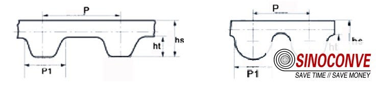
Pitch is the distance between the centers of two adjacent teeth, so a larger pitch means a physically larger tooth with a wider root. Tooth shear capacity scales with root area, which is why the load a belt carries per unit of width rises steeply as pitch increases. MXL at 0.080 inch pitch is a small-torque instrument profile. H at 0.500 inch pitch is the general industrial workhorse. XH and XXH at 0.875 and 1.250 inch pitch serve the slow, heavy end of the market. The step from L to H roughly doubles the pitch, and that is the step where most buyers discover their existing frame no longer fits.
Where XL and L Still Earn Their Place
These two sit in the middle of the family and cover a very large share of real machinery. A 0.200 inch XL drive is standard on small packaging, labelling and light conveyor indexing work. A 3/8 inch L drive turns up on machine tool feeds, printing units and agricultural implements. Both are inexpensive because both are mass produced, and a quarry or cement plant that buys a rubber conveyor belt for its main haul will normally standardize the small feeder drives on one of these two so that spares stay simple.
The Heavy End on Mill and Crusher Auxiliaries
XH and XXH drives appear on slow, high-torque duties such as kiln and mill auxiliary drives, large reciprocating pumps, and heavy process equipment where a chain would need continuous lubrication in a gritty environment. The trade is speed. These pitches are comfortable below roughly 1,500 rpm on the small pulley depending on tooth count, and they turn noisy and cord-stressed well before the belt's static strength is exhausted. If someone is trying to reach 3,000 rpm on XXH, the honest answer is a different pitch family rather than a wider belt.
| Pitch family | Typical small-pulley tooth counts | Duty it handles well | Practical speed ceiling | What we would flag in the field |
|---|---|---|---|---|
| MXL at 0.080 inch pitch | 10 to 40 teeth, frequently 14 to 20 in instrument drives | Positioning of very light loads below roughly 0.5 kW where smoothness matters more than torque | Comfortable into the thousands of rpm because tooth mass is small | Rarely worth stocking above 9 mm width, and tension is easy to overdo by hand. |
| XL at 0.200 inch pitch | 10 to 48 teeth, most commonly between 12 and 30 | Fans, small pumps, labelling heads and light conveyor indexing up to a few kW | Usually kept under 4,000 rpm at the small pulley | The cheapest family to standardize, so spares stay available for years. |
| L at 3/8 inch pitch | 12 to 48 teeth, mostly 18 to 30 in industrial use | Machine tool feeds, printing units, agricultural drives and general workshop equipment | Generally below 3,000 rpm on the small pulley | Buyers often jump to H when more width would have solved the same problem. |
| H at 0.500 inch pitch | 14 to 60 teeth, typically 20 to 40 | The industrial workhorse for compressors, mixers, blowers and heavier conveyor drives | Roughly 2,500 rpm and below unless the tooth count is high | Watch pulley alignment, because the wider tooth amplifies any angular error. |
| XH at 0.875 inch pitch | 18 to 60 teeth, commonly 24 to 40 | Slow, high-torque duties such as mill auxiliaries, heavy pumps and process drives | Usually below 1,500 rpm at the driving pulley | Needs a rigid frame because the drive develops large shaft loads. |
| XXH at 1.250 inch pitch | 18 to 48 teeth, mostly 24 to 36 | The heaviest low-speed transmission work where a chain would need constant oiling | Kept under about 1,000 rpm on the small pulley | Almost always a custom center distance, so confirm pulley stock before committing. |
03Metric Profiles: T5, T10, AT and GT
Metric pitch exists because a large part of the machinery world draws in millimeters and refuses to convert. T5 and T10 are the two workhorse metric pitches at 5 mm and 10 mm, and the AT and GT families sit on the same base pitches with a modified tooth geometry. Choosing between them is less about availability than it once was, but it still changes how much torque a given width will carry and how quietly the drive runs.
T5 and T10 as Straight-Flank Workhorses
A straight-flank trapezoidal tooth on a 5 mm pitch suits small automation axes, three-dimensional printers, and light indexing stations where the load is under about 2 kW and the pulley is small. T10 takes over when the torque grows: textile machinery, roller drives, woodworking feed units and medium conveyor auxiliaries are common homes for it. Both are stocked widely, and a competent conveyor belt supplier will hold both pitches in the widths your service team actually consumes instead of a full catalog that never moves.
The AT tooth form uses a shallower flank angle and a deeper engagement than the plain T profile, which reduces the chance of the belt climbing out of the pulley under shock load and slightly increases the shear area at the root. On paper the gain looks modest. In practice it matters on reversing drives, where the same tooth carries torque in both directions all day, and it is the reason one belt lasts three years while another develops root cracks in eight months.
GT and Curvilinear Geometry in Precision Work
Curvilinear teeth, sold under the GT and related designations, place a rounded, deeper contact patch on the pulley groove. The result is more teeth in contact at any instant, lower contact stress per tooth, and a noticeably quieter mesh at high pitch line speed. That is why the family dominates high-speed servo axes and spindle drives. It is also why those belts cost more. The tooling is harder to cut and the tolerance band on the flank is tighter, so the price premium buys quietness, load sharing and predictable backlash rather than raw torque.
| Metric family | Tooth form and engagement | Where it belongs on a machine | What the buyer pays for |
|---|---|---|---|
| T5 on a 5 mm pitch | Straight flanks with shallow engagement and a small tooth mass, tolerant of minor misalignment | Light automation axes, small indexing heads and instruments up to roughly 2 kW of transmitted power | Low unit cost and instant availability in stock widths |
| T10 on a 10 mm pitch | The same trapezoidal geometry scaled up, with roughly four times the tooth root area of T5 | Textile lines, roller drives, woodworking feeders and medium conveyor auxiliaries | Torque capacity without moving to a heavy imperial pitch |
| AT profiles on T and imperial bases | Deeper, shallower-flanked teeth that stay seated under shock and reversing torque | Reversing drives, punch presses, packaging indexers and any duty with frequent direction changes | Fewer tooth jump events and slower root crack growth |
| GT and curvilinear profiles | Rounded flank contact that spreads load across more teeth at once and lowers mesh noise | Servo axes, spindle drives and high-speed positioning where backlash and vibration are critical | Quieter running, better load sharing and tighter backlash control |
04How Pitch Governs Load, Speed and Noise
Buyers often treat pitch as a labelling convention and width as the real capacity knob. That instinct is backwards, and the reason sits in the geometry of a single tooth. Pitch controls how much root area one tooth presents to the pulley groove, how many teeth are in mesh at once, and how often the belt and pulley teeth strike each other per second. Load, speed and noise all fall out of those three facts.
Load Capacity Is Root Area Before It Is Width
Tooth shear strength rises with the square of pitch in the region of doubling, so moving from a 5 mm to a 10 mm pitch multiplies the area available at the root by roughly four. Only then does width add its linear contribution. A 25 mm wide T5 belt therefore carries far less torque than a 25 mm wide T10 belt, and no amount of tensioning changes that. When an industrial conveyor belt feeder drive is upgraded for a heavier surge load, the correct response is usually a pitch increase rather than a wider belt on the same pulleys.
Speed Limits Come From Impact Frequency
Every tooth engagement is a small impact. The frequency is the tooth count of the smaller pulley multiplied by its revolutions per second, so a 20-tooth pulley turning at 3,000 rpm produces 1,000 impacts per second. Cord fatigue and audible noise both track that number rather than the belt's linear speed. This is why two drives at the same 10 m/s pitch line velocity behave completely differently: the one with the coarse pitch and small pulley is striking far more often and absorbing far more energy per strike.
Coarser teeth displace more air and hit the groove face harder, so a heavy-pitch drive at moderate speed is louder than a fine-pitch drive doing the same work. We measured a 14 dB difference between a 20 mm pitch and an 8 mm pitch drive on the same frame at 1,700 rpm. If a drive has to sit next to an operator station, the quiet route is a finer pitch with more teeth, more width to recover the lost root area, and pulleys cut to a curvilinear form.
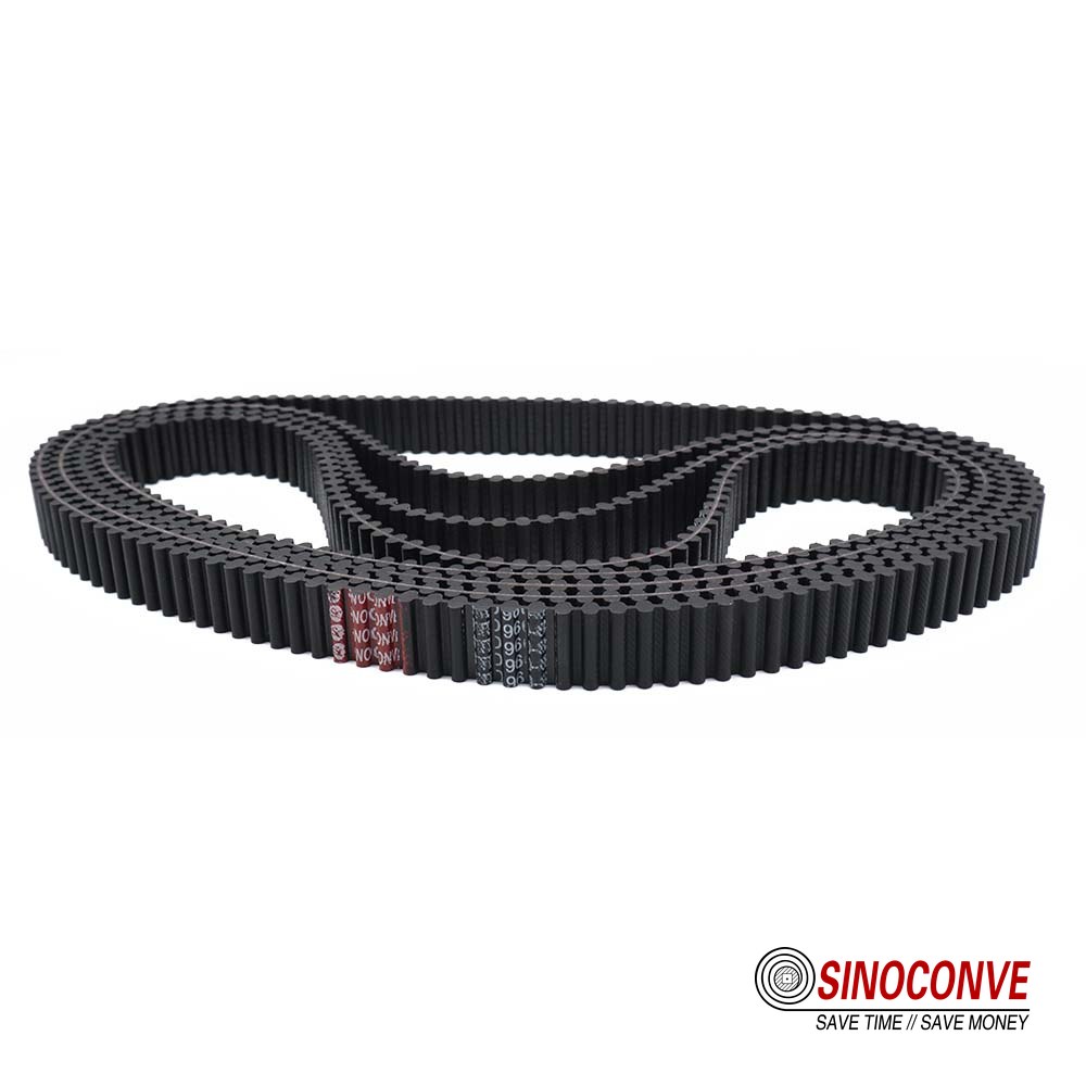
Pitch sets the tooth mass and the impact frequency, so two drives at the same belt speed can behave nothing alike.
05Cord Construction: Fiberglass, Aramid and Steel
The cord is the only part of a timing belt that resists tension, and everything else in the belt exists to hold it in position and protect it. Fiberglass, aramid and steel are the three families in industrial supply, and as a transmission belt manufacturer we specify all three depending on the duty. They are not interchangeable, and the differences show up in elongation, fatigue life, temperature tolerance and price in that order of importance.
Fiberglass Cord: Stiff, Cheap and Shorter Lived
Fiberglass has a high modulus for its cost, so belts built on it hold pitch well and resist creep under steady load. Its weakness is bending fatigue. Every trip around a small pulley flexes each cord, and glass filaments crack rather than flex, which is why a glass-cord belt on a very small pulley develops cord failure before the teeth wear out. Used within sane pulley diameters on moderate-duty drives it is the most economical choice, and it is what we recommend for fans, small pumps and general workshop equipment.
Aramid Cord: Fatigue Resistance With a Watch on Heat
Aramid tolerates repeated flexing far better than glass and carries a higher tensile load per unit area, which is why it dominates drives with small pulleys or heavy shock loads. It does have a temperature ceiling to respect. Sustained running above roughly 100 to 120 degrees Celsius at the cord line is not where aramid wants to live, and the limiting factor is usually the compound around the cord rather than the fiber itself. For reversing drives and high-torque servo axes, aramid is normally the correct answer.
Steel Cord: Length Stability Under Real Load
Steel cord gives the lowest elongation of the three and the best dimensional stability over years of service, which is why long-center-distance drives and multi-shaft synchronized machines use it. The trade is stiffness. A steel-cord belt has almost no give, so it punishes misalignment, passes more vibration into bearings, and demands a tension setting that is measured rather than estimated. A V-belt manufacturer working on the same plant usually confirms the pattern, since the stiffer the tension member, the less forgiving the drive becomes.
| Cord material | Elongation behavior under working load | Flex fatigue and temperature | Cost position and best fit |
|---|---|---|---|
| Fiberglass cord | High modulus and low creep, so pitch stays stable under a steady load with little re-tensioning | Bending fatigue is the weak point, and glass filaments crack on pulleys below the recommended minimum diameter | The lowest cost of the three, right for fans, pumps and general workshop drives |
| Aramid cord | Lower elongation than glass with far better recovery after repeated load cycles | Excellent flex fatigue, but sustained cord-line temperatures above roughly 100 to 120 degrees Celsius shorten life | Mid to upper cost, standard on small-pulley and shock-loaded drives |
| Steel cord | Very low elongation and the best dimensional stability across years of running | Handles heat and load well but is stiff enough to punish alignment errors and pass vibration into bearings | Highest cost, chosen for long centers and multi-shaft synchronization |
06What Precision Actually Means on a Toothed Drive
Precision is the word buyers use most loosely in the whole belt conversation. On a conveyor it usually means nothing at all, because the belt only has to carry material from one end to the other. On a toothed drive it means at least four different things. Position accuracy, repeatability, backlash and pitch tolerance are related but not identical measurements, and confusion between them is a common reason a drive is ordered correctly and still performs badly.
Position Accuracy, Repeatability and the Difference That Matters
Position accuracy is how close the driven shaft lands to the commanded angle on a single move. Repeatability is how consistently it returns to the same angle over ten thousand cycles. For an indexing machine, repeatability is almost always the requirement that actually matters, and it is usually two to four times tighter than the accuracy figure. A drive can hold 0.2 degrees of absolute accuracy and 0.05 degrees of repeatability, and that combination is fine for a packaging station. It matters because repeatability depends mainly on backlash and belt stretch, which you control, while absolute accuracy also depends on encoder mounting, pulley runout and thermal growth, which you inherit.
Backlash Accumulates From Five Separate Places
Backlash on a toothed drive is not a property of the belt alone. Clearance between belt tooth and pulley groove contributes some of it, pitch error spread along the belt adds more, and pulley eccentricity on its shaft takes a third share. Stretch of the tension member under load reversal, plus lost motion in the bearings and couplings either side of the pulleys, finishes the total. Since these contributions do not simply stack, two identical belts can produce different backlash on two different machines. When someone asks for a backlash guarantee on the belt alone, our honest answer is that we control three of the five contributions. Buyers who order wholesale conveyor belts and timing belts from one source usually get better consistency than buyers who mix sources.
| Requirement | What it actually measures | Value we would accept on a servo axis | How it gets verified on site |
|---|---|---|---|
| Positional accuracy | Distance between the commanded angle and where the shaft actually stops after one move | Within 0.2 degrees on a T10 drive with 24 teeth on the small pulley | Command a fixed index and read the shaft with an encoder or dial gauge over ten moves |
| Repeatability | Spread of the landing position when the same move is repeated thousands of times | Tighter than 0.1 degrees, and stable after the first fifty hours of running | Log the index position across a full production shift and watch the spread rather than the average |
| Backlash at the driven shaft | Lost motion read at the output when the drive is rocked by hand with power removed | Under 0.3 degrees of total lost motion at the output shaft | Clamp a lever and a dial gauge to the driven shaft, then rock the drive both ways |
| Pitch and length tolerance | Whether the accumulated tooth spacing along the belt matches the drawing over its whole length | Center distance held within plus or minus 0.3 mm of the calculated value on a new belt | Measure across a known number of teeth with a steel rule and compare with the nominal figure |
| Tooth mesh quality | How evenly load spreads across the teeth that are engaged at any one moment | At least six teeth engaged on the small pulley, with 10 being comfortable | Check the wrap angle from the layout drawing and mark wear patterns after the first inspection |
07Installation: Tension, Parallelism and Pulley Alignment
Everything in the previous two sections assumes the drive is built straight, and most drives are not. Installation errors do not usually stop a machine from running, which is exactly why they survive for years while quietly consuming belt life. We have measured 1.2 mm of angular misalignment between two shafts on a nominal 400 mm center distance in a plant that had replaced the same belt four times in two years. Nobody had checked the alignment, because the belt was the part that failed and the belt was the part that got replaced.
Setting Tension Without Guessing at It
Belt tension on a toothed drive is set low compared with a friction drive, because the teeth carry the load and the tension only has to keep them seated in the grooves. The working method is to push the belt at mid-span with a known force and measure the deflection, so on a 382 mm span we look for roughly 2 to 4 mm under a 100 N push and we re-check after the first day and again at about 500 hours. Under-tensioned belts jump teeth and wear the flanks; over-tensioned belts overload bearings and cords, and that damage stays silent until the cord lets go. A drive with an automatic tensioner still needs its initial setting verified, because an idler that never moves is usually seized rather than correctly loaded.
Parallelism is the second half of the same job. The two shaft center lines have to be parallel in both the horizontal and the vertical plane, and a drive can sit perfectly level while still being a degree out of parallel. On a 400 mm center distance, one degree of angular error shifts the belt sideways by roughly 7 mm across the span, more than most belts can absorb before the edge starts wearing against a flange. A straightedge held across both pulley faces catches that error in five minutes.
Tooth mesh is only as even as the shaft alignment underneath it, so the pulleys get checked before the belt is blamed.
08Worked Example: Sizing a T10 Indexing Drive
Numbers make a method concrete in a way that a table never does, so here is a drive we sized recently for an indexing conveyor on a packaging line. The motor nameplate gives 4 kW at 1,440 rpm and the driven shaft has to turn at 480 rpm, so the ratio is three to one. The frame fixes the center distance at about 380 mm, and the machine runs sixteen hours a day with a shock at each index. The customer asked for repeatability inside 0.1 degrees.
From Nameplate Torque to Width, Length and Tension
Start with torque rather than power, because tooth load is a force and force follows torque directly. Nominal torque at the motor shaft is 9,550 multiplied by 4 kW divided by 1,440 rpm, which is 26.5 Nm. A service factor of 1.6 for a moderate-shock, sixteen-hour duty lifts the design torque to 42.4 Nm. Choosing 24 teeth on the small pulley gives a pitch diameter of 24 multiplied by 10 mm divided by pi, or 76.4 mm, and the matching 72-tooth pulley runs at 229.2 mm. Belt speed works out at 5.76 m/s, which is well inside the practical envelope for T10.
Effective tension is twice the design torque divided by the small pulley diameter in meters, which is 2 multiplied by 42.4 divided by 0.0764, giving 1,110 N. Taking an allowable working tension of about 25 N per millimeter of width for this pitch and cord, the required width is 1,110 divided by 25, or 44.4 mm, so we move up to the next standard width at 63 mm and land at roughly 70 percent utilization. That headroom is deliberate. Shock at the index adds load that a nameplate figure never shows.
Belt length follows from the geometry. Twice the center distance, plus pi times the sum of the two diameters divided by two, plus the square of the diameter difference divided by four times the center distance, gives 1,255 mm, so the standard 126-tooth belt at 1,260 mm is the right call and the resulting center distance is 382 mm. Wrap angle on the small pulley is 157 degrees, which puts ten teeth in mesh. The effective tension therefore spreads as 111 N per tooth, or about 1.8 N per millimeter of width per tooth, which is roughly half the published allowable shear figure for this construction. Tensile strength of the belt, not tooth shear, is the limiting criterion here.
Tension is set so that a 100 N push at mid-span deflects the belt about 3 mm, then re-checked after the first day and again at 500 hours. On the precision side, the 24-tooth pulley indexes 15 degrees per tooth, so the requested 0.1 degrees of repeatability is under one percent of a single tooth position. That is achievable with an aramid cord, correct tension and total lost motion kept below 0.3 degrees, but only if the bearings and coupling are good. As a conveyor belt factory we treat the belt as the part we are responsible for and the rest as a conversation we have with the machine builder.
| Step | Calculation | Result | Check against the limit |
|---|---|---|---|
| Motor torque | 9,550 multiplied by 4 kW then divided by 1,440 rpm gives the nominal figure at the motor shaft | 26.5 Nm nominal, and 42.4 Nm after a 1.6 service factor | Service factor matches a moderate-shock duty of sixteen hours a day |
| Pulley sizing | 24 teeth multiplied by 10 mm pitch divided by pi, and the same for the 72-tooth driven pulley | 76.4 mm on the driver and 229.2 mm on the driven shaft | Both sizes are standard catalog pulleys, so no tooling is required |
| Belt width | 1,110 N divided by an allowable 25 N per millimeter gives 44.4 mm, rounded up to the next standard size | 63 mm wide belt at about 70 percent of allowable tension | Reserve capacity is left for the shock that arrives at every index |
| Belt length | Twice the center distance plus the circumferential term plus the diameter correction term | 1,255 mm calculated, so 126 teeth at 1,260 mm is selected | Final center distance becomes 382 mm, which fits the existing frame |
| Teeth in mesh | A 157 degree wrap on a 24-tooth pulley gives 24 multiplied by 157 divided by 360 | 10 teeth engaged under load | Above the six-tooth minimum and gives even load sharing |
| Tooth shear | 1,110 N spread across 10 teeth, then divided by the 63 mm of width | 111 N per tooth, or about 1.8 N per millimeter per tooth | Roughly half the published allowable, so the cord is the limiting part |
| Impact frequency | 24 teeth multiplied by 24 revolutions per second on the small pulley | 576 tooth impacts per second | Low enough to keep mesh noise and cord fatigue in a comfortable band |
| Tension setting | Deflection measured at mid-span under a known push on the 382 mm center distance | 2 to 4 mm under 100 N, re-checked at 24 and 500 hours | Low enough to protect bearings, high enough to stop tooth jump |
| Precision check | A 24-tooth pulley indexes 15 degrees per tooth, so 0.1 degrees is 0.7 percent of a tooth | Repeatability target of 0.1 degrees is reachable | Requires aramid cord, tension at spec and under 0.3 degrees of lost motion |
09Failure Modes and the Prevention That Actually Works
Timing belts fail in a small number of recognizable ways, and each one leaves a signature that points back to a specific cause. Reading that signature correctly saves money, because the alternative is a cycle of replacement without diagnosis. A conveyor belt distributor who works across many plants will usually recognize the pattern from a photograph faster than the maintenance team that lives with the machine every day.
Tooth Root Cracking, Tooth Jump and What They Tell You
Root cracking starts as a fine line at the base of the tooth on the loaded flank and grows until a tooth shears away. When a belt arrives with several cracked roots in a cluster rather than evenly spaced around the circumference, the cause is nearly always a repeated shock at the same point in the machine cycle, not a defective belt. When the cracks are evenly distributed, the drive is simply overloaded or under-tensioned for its whole duty and needs a width or pitch increase. Both cases are diagnosed the same way: mark the belt, run it, and see whether the failure site keeps returning to the same pulley position.
Tooth jump is different. The belt climbs out of the groove, loses register with the driven shaft, and usually takes a heavy impact when the machine tries to recover. Undertension is the first suspect, followed by too small a wrap angle and a driven inertia that decelerates the belt faster than the teeth can hold it. On a three-to-one drive with ten teeth in mesh, a badly tuned servo ramp can produce that condition without any mechanical fault at all.
Field note from our engineers: A sawmill customer sent back a 50 mm wide T10 belt with three teeth sheared off in a row every 1.2 m of length. The pitch of that damage matched one revolution of a jam-prone feed roller exactly. Changing the belt did nothing; adding a slip clutch to that roller ended the problem permanently.
Elongation, Back Wear and Edge Damage
Cord elongation shows up as a belt that can no longer be tensioned, and it is the one failure that cannot be fixed by an adjustment. Fiberglass cords creep faster than aramid or steel, especially at elevated temperature, so a drive that has to hold register for years needs the stiffer member. If elongation appears within a few weeks rather than a few years, look for a pulley below the minimum recommended diameter, because small pulleys flex the cord far more per revolution and accelerate that process. Related reading on how material handling hardware behaves under the same punishment is available in our guide to conveyor belt tracking, which covers the same alignment logic that governs a toothed drive.
Back wear is the quiet one. Abrasive dust working between the tooth root and the pulley groove grinds the backing compound away tooth by tooth, until the compression section is thin enough to lift clear of the pulley under load. Prevention costs almost nothing: a sealed guard, a wipe on the return strand in dusty areas, and a periodic check that no material is packing into the groove roots. Edge damage is the mirror image and points at misalignment, a bent flange, or a trapped foreign object.
10Procurement and Acceptance Fields for a Toothed Belt
An order for an industrial timing belt that states only the pitch and the length is an invitation to a mismatch, because the belt that arrives may have the right tooth count and the wrong cord. Five extra lines on the purchase order prevent almost every dispute we have been asked to mediate between a plant and its supplier.
What the Order and the Incoming Inspection Must State
The order should name the pitch and tooth form exactly as they appear on the pulley drawing, and the belt length in teeth as well as in millimeters. Width has to carry its tolerance, the cord material has to be stated, and the compound hardness range has to be pinned down.For anything going onto a food line, add the applicable contact requirement; for anything near a hot process, add the continuous and peak temperatures separately, because a belt rated for 100 degrees continuous is not a belt rated for 150 degrees for an hour every shift. Buyers comparing a timing belt against a friction drive will find the same discipline applies across our timing belt range and the equivalent polyurethane timing belt options used on lighter automation work.
Inspection on arrival takes twenty minutes and needs nothing more than a steel rule, a straightedge and a durometer. Measure across a fixed number of teeth to confirm pitch, then lay the belt flat and check that it runs straight rather than arcing to one side, which points at uneven cord tension. Check the width at three points and compare backing hardness with the specified range. Record the batch code, because the next delivery will be judged against that record rather than against memory.
Repeat orders deserve one more field: a note requiring the same construction and the same batch control as the first shipment. Consistency is worth more than a marginal price difference on this kind of component, and the way to get it is to ask for it in writing rather than to hope for it.
11Field Notes From Drives We Have Rebuilt
Twenty years of service work leaves a set of habits that no data table teaches. One of them is to measure before believing. On a cement plant clinker conveyor we were called to inspect a "bad batch" and found the drive perfectly sound: the real problem was 2 mm of wear in a pillow block bearing that let the driven pulley sit at an angle under load and back again when the load came off. The belt had been replaced four times for a fault that lived in the frame.
Another habit is to treat belt failure as a symptom with a timeline. One that fails within a week was installed wrong or is fighting a jam, one that fails after a year is usually undersized for the duty or living in an environment nobody described to the supplier, and one that fails after five years simply reached the end of its fatigue life. Sorting those three cases before ordering anything prevents most of the wasted spending we see.
Pitch measurement and cord tension records are what make a replacement belt behave like the one it replaced.
Field note from our engineers: The most useful single number a maintenance team can hand us is the center distance measured on a new belt and then re-measured after 500 hours. That pair of readings tells us more about whether the drive is stretching, slipping or simply aging than any photograph of a worn tooth.
12When a Toothed Drive Is the Wrong Answer
Not every problem is a timing belt problem, and saying so early is part of the job. If the two shafts do not need a fixed phase relationship, a friction drive will be cheaper, quieter in some installations and far more tolerant of shock. If the speed is very high and the torque is very low, a flat belt on crowned pulleys may outlast a toothed belt by years. If the duty involves continuous slip as a design feature, a clutch or fluid coupling belongs in the train instead.
Shaft loading is the other deciding factor, because a toothed belt needs real tension to stay engaged and that tension lands on both bearings. On a long overhung shaft with a small bearing, the moment produced by belt tension can be the reason a bearing fails every eight months. Comparing the same drive against a V-belt arrangement, which tolerates much looser tension, is sometimes the cheaper engineering answer.
Where the choice does fall on a toothed belt, buy the correct one rather than the nearest one. Pitch, cord and precision are a chain of decisions, and breaking any link moves the failure somewhere else in the machine where it will cost more to find.

13Frequently Asked Questions
What pitch should I choose for an industrial timing belt drive?
Start from the torque at the driven shaft and the tooth count you can physically fit on the small pulley, then pick the smallest pitch that carries that torque without going below six teeth in mesh. In our experience a 5 mm pitch covers light automation, 10 mm covers most indexing and roller work, and anything above 20 mm belongs on slow, heavy drives. If the calculation lands within ten percent of the limit, move up one pitch rather than adding width.
Is a wider belt a substitute for a coarser pitch?
No. Width adds load capacity in a straight line, while pitch adds it roughly with the square of the tooth size, so the two are not interchangeable. Width is also limited by the pulley face and by the housing space you have. When a drive runs out of capacity, the usual correct move is a pitch increase with new pulleys, not a wider belt on the same wheels.
How much tension should an industrial timing belt have?
Just enough to keep the teeth seated, and no more. We set tension by measuring mid-span deflection under a known push, typically 2 to 4 mm under 100 N on a 380 mm center distance, then re-check after the first day of running and again at about 500 hours. Over-tension is more common than under-tension in plants that treat a toothed belt like a friction belt.
Which cord material lasts longest?
It depends on which failure you are trying to avoid. Steel gives the lowest elongation and the best long-term register but punishes misalignment. Aramid survives flexing and shock better than the others and is the usual choice for small pulleys and reversing drives, provided cord-line temperatures stay under roughly 100 to 120 degrees Celsius. Fiberglass is the economical option where the duty is steady and the pulley diameters are reasonable.
Can an industrial timing belt hold 0.05 degrees of repeatability?
It can, but the belt is rarely the limiting factor. On a 24-tooth pulley at 10 mm pitch, one tooth position is 15 degrees of output rotation, so 0.05 degrees is well under one percent of a tooth and requires total lost motion below roughly 0.15 degrees. That means tight pulley fit, good bearings and a stiff frame. If any of those is loose, no belt will deliver the figure.
Why does my timing belt keep jumping teeth?
Nine times out of ten it is tension that has dropped, either set too low at installation or lost as the cord crept. The other reason is a deceleration event the drive cannot absorb, such as a jam releasing suddenly or a servo ramp too aggressive for the inertia involved. Check tension first, then the wrap angle and the driven inertia.
Do toothed belts need lubrication?
None at all, and adding oil is actively harmful because it attracts abrasive dust into the tooth roots and attacks the rubber compound. That dry-running property is one of the main reasons a toothed belt replaces a chain on equipment where product contamination matters. Maintenance is limited to checking tension, alignment and groove cleanliness.
What should I put on the purchase order to get a consistent belt?
Pin the specification, not just the size. The order needs the pitch and tooth form exactly as they appear on the pulley drawing, together with the length in teeth and in millimeters. Width has to carry a tolerance, and the cord material has to be named, because two belts of the same size can differ completely in how much they stretch. Add the compound and its hardness range plus the temperatures the belt has to survive, require the same construction and batch control as the first shipment, and record the batch code on arrival so the next delivery is judged against evidence rather than memory.
When is a chain or a V-belt the better choice?
Choose a chain when the torque is very high, the speed is low and lubrication is available, and choose a V-belt when the shafts do not need a fixed phase relationship or when bearing loading has to stay loose. Our article on heavy duty rubber conveyor belt duty covers the same trade-offs from the material handling side. The toothed belt wins whenever the driven shaft has to arrive at a defined position and stay there.
Related Products You May Need
- Industrial timing belts in imperial and metric pitches, cut to length or endless.
- PU timing belts for lighter automation, packaging heads and cleanroom-style duties.
- V-belts for drives that do not need a fixed phase relationship between the two shafts.
- Rubber conveyor belts for the material handling side of the same plant, in EP and NN constructions.
- Full product catalog covering belt, roller and pulley lines for mining, quarry, cement and port projects.
Related Blog Posts
- Heavy duty rubber conveyor belt performance in mining duty and how it compares with lighter constructions.
- EP conveyor belt tracking guide for the alignment logic that toothed drives share.
- Conveyor roller types, materials and load ratings explained for maintenance engineers.
- Abrasion resistant belt selection for quarry and steep angle conveying in daily service.
- Dust resistant belt options for drives and conveyors working in fine, abrasive material.