

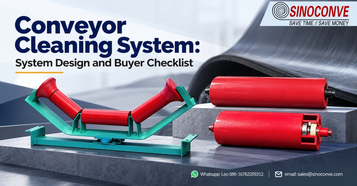
A conveyor cleaning system is defined by its boundary long before it is defined by its hardware. Draw the line where material leaves the belt at the discharge pulley, carry that line along the return strand and past the transfer points, and stop it where the recovered material finally reaches a bin, a dewatering arrangement or a pump sump. Do that first and most of the component arguments settle themselves. Skip it and you end up with blades fighting one another, slurry pushed out of one problem area and into the next, and a maintenance crew that has quietly stopped bothering with the cleaning station at all.
We have been pressing belting and building rollers, scrapers and vulcanizing equipment in Ningbo for more than thirty years, and the calls we take from quarry, cement and port operators almost never open with a part number. They open with a symptom: a growing pile under the tail pulley, a belt that will not track after a cleaner was added, a sump pump running every shift. Nine times out of ten those calls turn out to be scope problems rather than component problems, which is why this page is built around boundaries, interfaces and buy-off criteria instead of around blade geometry.

Think of the subsystem as everything between two hard limits. The upstream limit is the moment the belt releases its load, normally at the discharge pulley but on a stacker or a shuttle conveyor it may be a tripper or a plough. The downstream limit is the point at which the material you have recovered is handed back to the process stream, dropped into a bin, or passed to a dewatering arrangement. Everything between those two limits belongs to the cleaning scope and has to be designed as one package. Everything outside them belongs to somebody else, and holding that line is what keeps a modest retrofit from turning into an unplanned capital project.
01Why the Cleaning Subsystem Has to Be Scoped as One Package
Most plants still buy cleaning hardware the way they buy bearings, one line item at a time whenever an inspector writes something up. That approach survives perfectly well on a short transfer conveyor, and it collapses on anything longer than about 200 m or carrying a material whose moisture content runs above roughly 8 percent. The collapse is rarely caused by a weak component. It is caused by two components that each do their job competently and undermine each other, and the textbook example is a secondary cleaner mounted so close behind the primary that it scrapes the same flattened film the primary has just pressed onto the cover.
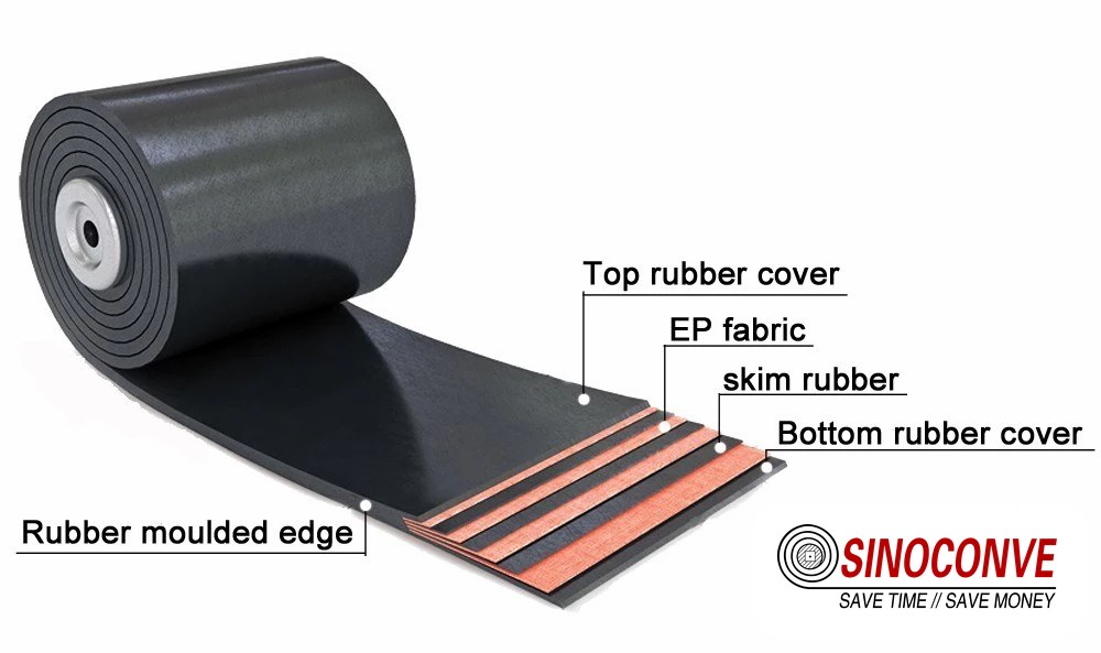
Belting choice sits inside this boundary too, and buyers often forget it. As a conveyor belt manufacturer we press covers from 2 mm to 12 mm, and we can tell you exactly what a 4 mm cover looks like after three years of phosphate slurry. A cover that is too thin for the duty deforms under scraper pressure long before the blade wears out, while an unnecessarily thick cover simply gives fines more rubber to lodge against. Neither outcome is visible on a purchase order, and both of them show up in the first quarterly clean-out.
The second thing a properly scoped boundary buys you is an honest bill of materials. When the same source quotes as a conveyor belt supplier and also supplies the rollers and cleaning hardware, the return strand appears as one line instead of four, and nobody on the project can claim that the interface is somebody else's problem.
In our experience that clarity is worth more than a discount on any individual item, because interface arguments are what turn a two-week installation into a two-month one.
02System Boundary and the Interfaces That Actually Decide It
Four interfaces govern whether the subsystem performs, and on a typical project each of them is owned by a different drawing. When those drawings are issued independently, the cleaning scope absorbs every accumulated tolerance error, because it is normally the last item installed and the first item blamed. We ask for all four to be reviewed in one meeting and we bring the belting, roller and structure data with us, because by the time steel is in the ground the argument is already three months old.
The Load Point, the Chute and the Skirt Boards
The chute and its skirt boards set the conditions the cleaning subsystem has to live with. A skirt gap of roughly 20 to 30 mm closed by a proper rubber seal keeps the load centred and keeps loose material out of the cleaner's working area, whereas a 60 mm gap on a 1,200 mm belt will feed a continuous trickle of fines past the skirt and under the primary blade for the whole shift. If the skirt is open at the bottom, no amount of blade pressure will fix the pile that forms beneath it, and the correct engineering answer is to close the skirt rather than to add a second cleaner to chase the leakage.
The Return Strand, the Idlers and the Discharge Endpoint
The return strand carries the consequences of everything that happens upstream. Return idlers that have drifted out of alignment tilt the belt and change the contact angle at the blade, so we inspect roller alignment and bearing condition before we size a single component. On a 1,400 mm belt running faster than about 3.5 m/s, one seized return roller can lift the belt locally by several millimetres and open a gap beneath the blade that no spring tension will ever close. Belts that are wandering badly enough to need a dedicated industrial conveyor belt review of the joint and camber generally cannot be cleaned reliably until that foundation is corrected.
The discharge endpoint is the third face of the same interface, and it is the one most often left off the drawing entirely. Whatever the subsystem recovers has to arrive somewhere with a defined capacity and a defined removal route. When that endpoint is a sump, its volume, its pump duty and its clean-out access all belong to the cleaning scope even though the civil work usually does not.
We have opened sumps sized by eye for a bucket and found them receiving close to a tonne of solids every shift, which is a design failure rather than an operating one. Splitting the return strand across a set of properly aligned conveyor roller assemblies is the upstream half of getting this right, and the material profile of the site matters as much as the equipment, which is why the same arrangement behaves differently in a quarry and mining circuit than in a port.
03Component Combination Matrix: Which Hardware Covers Which Zone
Component families are not interchangeable, and the fastest way to lose a commissioning argument is to swap one for another on price alone. A plough and a primary scraper both remove material from the same belt, yet they operate on different zones, tolerate different materials and fail in different ways. The matrix below is the version we carry into site meetings. It is deliberately written as a set of conditions rather than a shopping list, because the question is never which component is best in the abstract but which combination covers the whole strand without overlap.
Reading the Matrix as a Chain of Handoffs
Work down the table and you are really reading a sequence of handoffs. Each device takes the material left by the one before it and passes on what it cannot hold, and the subsystem is healthy when that residue is small enough for the next device to deal with. It becomes unstable when two rows claim the same zone, which is what happens when a secondary cleaner is bolted onto a primary's mounting arm rather than staggered on its own bracket, or when a plough sits directly under a spray bar and receives material the water has just loosened. Combination decisions should always be recorded against the zone they cover, not against the equipment list.
| Component family | Strand zone it is designed to cover | Conditions that justify fitting it | Conflict risk with adjacent equipment | First sign it is underperforming |
|---|---|---|---|---|
| Primary scraper with a polyurethane or tungsten tip | The discharge pulley face, immediately where the load leaves the belt | Free-flowing to mildly sticky bulk, at belt speeds up to roughly 4.5 m/s | Presses the same film the secondary blade must lift when spacing falls under one belt width | The carryback film stays glossy and even across the full belt width |
| Secondary scraper on its own bracket | The return run about one belt width downstream of the primary | Fine or moist material that a single blade cannot lift from wet rubber | Interferes with return idlers whenever the mounting arms are not staggered | A visible ridge of fines rides the idler face just behind the blade |
| Plough or V-plough on the return strand | The section of return belt ahead of the tail pulley, upstream of the tail roller | Coarse material that has already reached the underside of the belt as lumps | Chews sidewall skirt or chevron profiles if it is fitted to a profiled belt | Lumps accumulate at the plough wing instead of at the discharge chute |
| Spray or wash box arrangement | A transfer point or a dedicated enclosure on the return strand | Dust suppression and sticky mineral residue where water is available and drainage exists | Wash liquor is pushed into the sump because the boundary stops at the nozzles | Water pools in the trough and solids build up under the washing zone |
| Air knife or blower bar | Dry bulk handling where the belt surface must stay absolutely dry | Free-flowing powders, grain and dry cementitious material on enclosed lines | Adds airborne dust that the sealed chute downstream then has to absorb | A visible dust plume appears at the point where the knife discharges |
| Brush roller on a driven shaft | The return strand, where fibre, light debris or fine dust clings to the surface | Textile, wood chip and light-duty handling on lower-speed belts below about 3 m/s | Bristle wear accelerates sharply on abrasive aggregate once speed rises | Brush tips flatten and polish the cover instead of sweeping it clean |
| Vibratory or impact-assisted device | The loading zone and the first few metres of the carrying strand | Sticky clay or organic material that adheres in sheets rather than as a thin film | Shakes material loose and drops it back onto the belt when amplitude is too high | Dislodged material reappears on the return strand within a few metres |
Two rules fall out of this table whenever we apply it on site. The first is that a rubber conveyor belt with a soft, high-elongation cover will forgive a slightly over-tensioned scraper for a few weeks and then fail suddenly, so tension should be set to the belt rather than to the hardware. The second is that adding a component to a zone already covered by another is almost never neutral; it either doubles the removal rate briefly or creates a new wear path, and the second outcome is far more common.
04Primary and Secondary Scrapers: How the Work Is Divided
A single blade removes most of what a dry, free-flowing material leaves behind, and two stages become worthwhile the moment the residue starts behaving like a coating instead of a crumb. The division between the two is a division of zone and of particle size, not a hierarchy of quality. The primary stage meets the belt while the load is still leaving it and deals with the bulk; the secondary stage meets the belt a little later and deals with what the first stage could not hold. Buyers who treat the second blade as an upgrade of the first usually end up paying twice and covering one zone.
Where the Primary Stage's Responsibility Ends
The primary stage hands over a belt that is free of loose material but not necessarily free of moisture, and that handover point is the real boundary. Anything still adhering after the primary has passed is by definition in the secondary stage's zone, or in the zone of whatever follows the secondary. When a plant reports that the primary is underperforming, our first question is usually whether the belt at that point is genuinely wet, because a rubber cover carrying a water film behaves differently from one carrying a dry dust layer.
This is also where drive-side equipment enters the picture; on lines where the cleaning station shares a frame with a crusher drive, belt and pulley condition tend to be managed together, and we often meet transmission belt manufacturer specifications in the same maintenance plan.
Where Blade Pressure Belongs in the Specification
Blade pressure is an interface parameter and should be written into the specification as one, because it is the load the cleaning subsystem transfers into the belt, the pulley and the structure. Our default working band for a polyurethane tip sits between roughly 20 and 40 N per 100 mm of belt width, and the figure has to be checked against cover hardness rather than picked from a catalogue page.
Push a 60 Shore A cover at the top of that band and you are polishing the rubber; set the same blade at the bottom of the band on an abrasive aggregate duty and you simply leave residue behind. The pressure figure, the cover grade and the expected life belong on the same datasheet line.
05Where the Return Strand Cleaner Sits in the Subsystem
The return strand is where cleaning stops being a single station and becomes a chain of stations, because material that escapes the discharge pulley has the length of the machine to travel before it reaches the tail. Within our boundary, the return strand is treated as a transport problem: what arrives there, how much of it arrives, and which device is responsible for the last few grams. The detailed geometry of that equipment, including where each unit mounts and how it is diagnosed when it misbehaves, is covered in our companion page on return side belt cleaning, and we refer to it rather than repeat it here.
What matters at the design stage is the handover: the discharge station should deliver a belt whose remaining load is small enough that the tail-end arrangement can process it without a second handling step. Where that handover is measured in tens of grams rather than kilograms per shift, a lighter and cheaper arrangement is usually sufficient. When buyers are consolidating a multi-conveyor project into one order, the return strand is also where a wholesale conveyor belts enquiry tends to grow fastest, because every additional conveyor adds its own chain of stations.
06Choosing the Medium: Water, Air or Neither
Whether the subsystem uses water, compressed air or nothing at all is a boundary decision with consequences that reach well past the cleaning station itself. Water brings drainage, corrosion and a wet load into the process; air brings dust, noise and power draw; doing neither brings a residue that must be tolerated and managed. The three routes are not ranked, and the commonest mistake we see is a plant adding a wash stage to solve a carryback problem that was actually a chute problem, then discovering that it has created a discharge problem in exchange.
The Decision Rule We Apply Before Any Spray Is Fitted
Our rule is straightforward. If the material is a dry powder or a free-flowing mineral and the belt must leave the station dry, air wins and water is not on the table. If the material is a sticky mineral slurry and dust control is a legal obligation rather than an aesthetic one, water wins, but only where the boundary has been extended to include the discharge endpoint. In between those two cases, mechanical removal is normally the cheapest answer and the one least likely to generate a new problem downstream. The engineering detail behind the wash option, including nozzle layout and water consumption, sits in our dedicated spray cleaning article; here we only decide whether the medium enters the scope.
There is a commercial dimension to the same decision. A wet subsystem changes what belt you should be buying, and the choice between a standard black cover and a lighter, washable surface is one of the most frequent questions we handle as a conveyor belt distributor. On inclined sections the water route and the profile route frequently collide, because a surface that holds material on an incline also holds the water you have just sprayed onto it.
07Brush Rollers and Vibratory Devices: the New Problems They Introduce
Brush rollers and vibratory devices earn their place on materials where a blade cannot get purchase at all, which usually means fibre, light debris or a cohesive clay that smears rather than shears. They are rarely the first choice and they are almost never free, because both of them change the environment around the belt rather than simply removing material from it. A brush throws dust and fibre into the air, and a vibratory unit re-suspends material that had already settled. Both effects have to be absorbed somewhere inside the boundary, and if nothing in the design absorbs them the cleaning subsystem has moved the problem rather than solved it.
What a Brush or Vibratory Station Changes Downstream
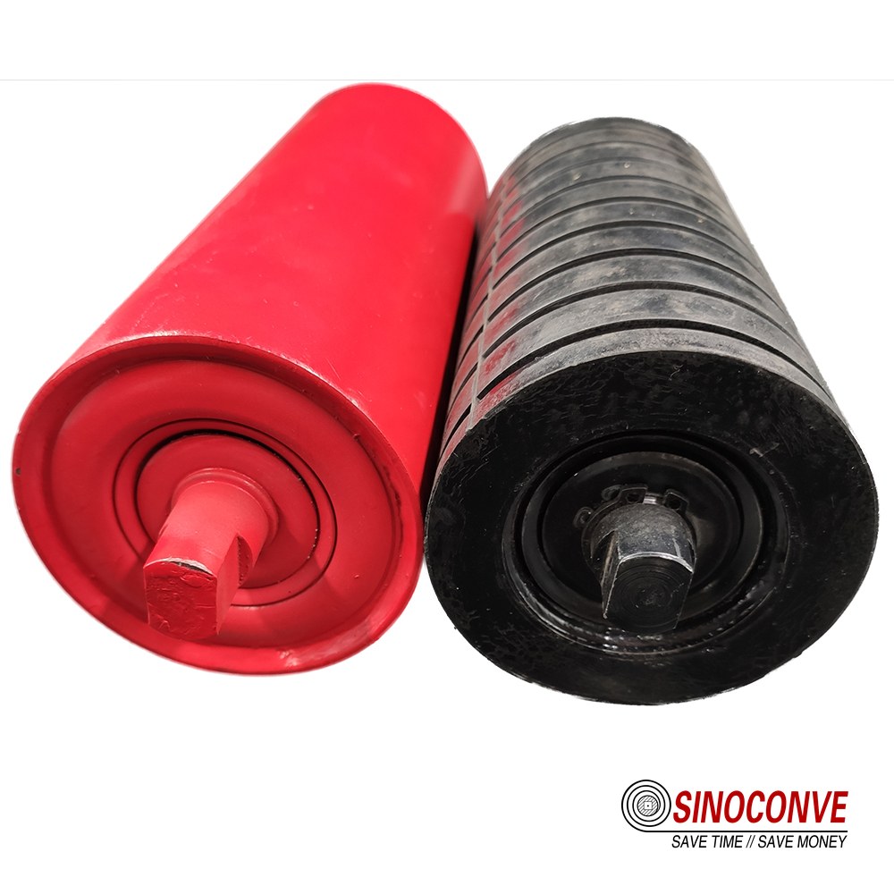
The downstream consequence is nearly always an enclosure question. Once a brush is fitted, fine dust that previously sat on the return strand is airborne, and the idler bearings immediately behind the station become the components that pay for it; sealed designs earn their cost in exactly this position, and we route buyers with fine-dust duties toward our notes on the sealed conveyor roller option.
A vibratory device carries a different penalty, because the energy it puts into the belt travels in both directions, and a poorly damped unit will loosen the fasteners of every structure within a few metres.Both families should be specified with their enclosure and their damping in the same scope, not added later as an afterthought once the dust complaints arrive. That single discipline is what separates a cleaning subsystem that works from a collection of devices that happen to share a frame, and it is one of the habits we have carried over from our own conveyor belt factory floors.
08Design Constraints That Move the System Boundary
Seven variables decide how far the boundary has to stretch, and they are worth tabulating because each one, pushed past a certain point, stops being a tuning question and becomes a scope question. Speed and width set the mechanical limits of the hardware. Moisture and stickiness decide whether mechanical removal can be expected to work alone. Space, water, dust and temperature decide whether the design you have drawn can actually be installed, adjusted and trusted in the environment that exists. The table below is the envelope we plan inside, and the last column is the honest answer when a project sits outside it.
The Envelope We Plan Inside
| Design variable | Range we plan around | What changes outside that range | How the subsystem compensates |
|---|---|---|---|
| Belt speed at the cleaning station | Roughly 1.0 to 4.5 m/s for scraper-based cleaning | Blade impact loads rise and tip wear accelerates noticeably | Move to a segmented tip and shorten the inspection interval |
| Belt width across the station | 500 to 2,400 mm with segmented blades | A single continuous blade cannot follow crown or splice variation | Split the contact face so each segment follows the cover locally |
| Material moisture content at the load point | Up to about 8 percent by weight for mechanical cleaning alone | Residue turns into a coating and blades stop lifting it cleanly | Extend the boundary to include a wet stage and its endpoint |
| Material stickiness and cohesion | Free-flowing to mildly cohesive on a two-stage arrangement | Cohesive clay builds on the cover and passes the blade as a film | Add a loading-zone device and reconsider the cover compound |
| Space behind the discharge pulley | A minimum of about 400 mm of clear access for tools | Blade changes and tension adjustments cannot be done safely | Resolve chute geometry early, while the steel is still being detailed |
| Water availability and drainage | A plant that already has drainage and dust control in place | Wash liquor and airborne dust become new site problems | Include the enclosure and discharge point inside the boundary |
| Temperature at the cleaning station | Ambient up to roughly 80 degrees Celsius on hot-process lines | Standard polyurethane softens and blade life falls away quickly | Specify a heat-rated tip and a matching cover grade together |
Where Space and Temperature Bite First
Space and temperature are the two constraints that most often force a redesign, and they bite at opposite ends of the project. Space bites during detailing, when a 400 mm access requirement turns out to conflict with the chute stiffeners, and it is far cheaper to move a bracket than to move a chute. Temperature bites later, when a specified polyurethane tip begins to soften and the cleaning station starts leaving residue on a duty it handled perfectly in winter.
On hot-process lines we ask for the actual surface temperature at the station rather than the process temperature, since a belt that leaves a kiln at 120 degrees is often down to 70 or 80 degrees by the time it reaches the cleaning hardware. Where the same frame drives auxiliary equipment, heat exposure becomes a shared problem, and the V-belt manufacturer data for the drive is usually the first place the temperature effect shows up.
09How This Page Divides Work With Our Other Cleaning Guides
We already publish four pages on cleaning, and this fifth one exists because none of them defined the boundary. Rather than restate them, here is the split we actually apply when a customer sends a query, because it saves everybody a week of email.
The Division of Labor Across Five Pages
The first of the four, on cleaning methods and schedules, answers whether mechanical cleaning is the right family of solution at all and covers the cases in which a scraper simply will not work. It is the page to read before any equipment decision, and it deliberately stops short of system architecture. The second, on spray cleaning, goes deep into nozzle selection, water consumption and wash-box layout, which is exactly the detail we exclude here; we treat water only as a boundary decision about whether the medium belongs in the scope.
The third page, on return side belt cleaning, owns everything that happens under the discharge pulley and along the return run, including mounting positions, blade angles, wear diagnosis and the pressure figures we only mention in passing. If your question begins with the words where should this unit be fitted, that page is the right one. The fourth, on reducing carryback sludge, deals with the wet end of the problem, including settling, water recovery and the handling of the material once it has been converted into sludge.
This page sits above all four and answers a different question. It asks where the subsystem starts and finishes, which component families cover which zone, what the interfaces with the chute, the idlers and the sump must guarantee, and what you should write into a purchase order so that the answer is falsifiable.
Nothing here teaches cleaning; the four linked pages do that. What we have tried to build is the frame that tells you which of them to open first, and which of them to hand to your structural and civil designers on the same day.
10Capacity and the Endpoint: Where the Recovered Material Actually Goes
The endpoint is the part of the subsystem that nobody photographs and everybody has to live with. Its capacity sets the real limit on how much cleaning the design can attempt, and it is the component most often sized by feel rather than by calculation. A simple first estimate is worth doing on the back of an envelope before any hardware is selected: multiply the carryback rate per metre of belt width by the belt width and the number of operating hours, and you have the daily tonnage the endpoint must accept.
On a 1,200 mm belt carrying 20 g per metre of width per pass, a 3.6 m/s belt running 16 hours produces a little over one tonne of recovered material per day. If the sump on the drawing holds half a tonne, the design has already failed and no blade choice will rescue it.
Sizing the Endpoint Before Selecting the Hardware
We prefer to size the endpoint first and work backwards, because it constrains everything else. A bin or a screw conveyor has an obvious capacity and a defined discharge, so it is easy to justify. A sump or a settlement pit does not, and it quietly becomes the limiting factor within one season. Where the boundary feeds a pit, we ask two questions that are rarely on the enquiry form: what removes the solids, and how often can that removal realistically be done by the crew on shift. Where the answer is uncertain, the honest design move is to shrink the tonnage entering the endpoint by improving the upstream stations, which is a subsystem decision rather than an equipment decision.
Ports and bulk terminals make this easier to see than most plants, because their transfer points are closely spaced and the recovered material has to be accounted for in a port bulk material handling environment where spillage has a direct commercial cost.
On longer machines the same logic pushes the design toward shorter belts and more transfer points, which is often the opposite of what the layout drawing suggests. Each transfer point resets the belt and gives the subsystem a fresh start, so the carryback that reaches the endpoint is bounded by one belt length rather than by the whole run. Before any order is placed, it is worth confirming that the endpoint, the drainage and the removal route all appear on the same drawing, because a subsystem whose output has nowhere to go will simply redistribute itself across the site.
11Operating and Maintenance Strategy for the Subsystem
Once the boundary is fixed, maintenance stops being a matter of taste and becomes a schedule with thresholds attached to it. The strategy we hand over with a cleaning subsystem is deliberately small, because a long inspection list is a list nobody completes. Four checkpoints, each with a number that triggers action, cover most of what actually goes wrong. The intervals below assume a two-shift operation on abrasive bulk; a single-shift line can stretch them, while a 24-hour port duty should shorten them.
Inspection Intervals and the Thresholds Attached to Them
| Check point | Interval we recommend | Threshold that triggers action | How the reading is taken |
|---|---|---|---|
| Blade tip wear at the primary station | Every 500 operating hours or at each planned shutdown | More than about 10 mm gone from a 15 mm tip | Measured with the belt stopped and the guard removed |
| Tension bolt travel and locking | Monthly in the first quarter, quarterly afterwards | Remaining adjustment below a quarter of the thread length | Recorded on the same sheet as the tip measurement |
| Carryback mass on a sampled belt length | Weekly for the first month of operation, then monthly | A gain above roughly 15 g on a 300 mm full-width sample | Sample taken about 2 m downstream of the station |
| Sump solids level and pump cycling | Daily through the wet season, weekly for the rest of the year | The pump runs continuously instead of cycling on a level switch | Compare against the clean-out level marked on the drawing |
| Return idler alignment and bearing temperature | Quarterly, with a thermal check on any suspect bearing | A shell running more than 30 degrees above ambient | Checked against the belt line before blaming the blade |
Field note from our engineers: in a 42 degree Celsius clinker gallery we once measured 96 degrees Celsius on the belt surface 300 mm after the discharge pulley, while the maintenance log still recorded the process temperature. The blade had been specified for 80 degrees and was being replaced every three weeks. Moving the specification onto the measured surface temperature took the replacement interval past four months, and no other change was made to the station.
Why the Thresholds Matter More Than the Intervals
Most cleaning problems we are asked to diagnose turn out to be a maintenance decision taken too late rather than a design error. A tip worn past its limit stops scraping and starts burnishing, and once burnishing has begun the residue is harder to remove with a new blade than it would have been with the old one kept in adjustment. The thresholds above exist to move the decision earlier rather than to fill a logbook, and the reference data for the rollers that carry the strand is worth reading alongside them, particularly the load and sealing ratings in our conveyor roller guide.
12Procurement Checklist: the Fields Every Enquiry Should Fix
Most of the quotations that go wrong do so because the enquiry left one of the fields below blank, and the supplier filled the gap with a reasonable assumption. That is not dishonesty; it is arithmetic on incomplete data. Fixing the fields costs one site visit and one afternoon of measurement, and it removes almost all of the dispute risk from the order. The list is also the fastest way to compare competing offers, because quotations that answer different questions cannot really be compared on price. All of it can be handled as a single enquiry through our product catalogue if you would rather not split the strand across suppliers.
Fields to Fix Before You Request a Price
| Enquiry field | Why it changes the quotation or the design | What a usable answer looks like on paper | Who normally owns the figure |
|---|---|---|---|
| Measured belt speed and belt width at the station | Speed changes blade impact loading and the tip family that suits it | One measured figure for each, taken at the machine rather than from the nameplate | Maintenance or the site engineer who runs the line |
| Material description with moisture content and bulk density | Moisture decides whether a mechanical stage can work on its own at all | A moisture test result and a sieve or size range, not a trade name | Process or laboratory staff, usually from the quality team |
| The strand zone each quoted item is expected to cover | Overlapping zones are the most common source of duplicated spending | Every quoted line mapped to a zone marked on the conveyor arrangement drawing | The design engineer who owns the cleaning scope boundary |
| Access dimensions and available mounting space | Access decides whether the station can be maintained at all after installation | A measured distance from the pulley face to the nearest obstruction, in millimetres | Site survey, jointly with the chute fabricator |
| Ambient temperature and measured belt surface temperature | Temperature drives tip material selection and the cover grade beside it | Surface temperature at the station under normal load, not inside the process route | Process engineering, verified on site with a contact probe |
| Condition of the interfaces, including skirt gap and idler alignment | Poor upstream conditions are always blamed on the newly supplied hardware | A skirt gap figure in millimetres and an alignment check with the date it was taken | Maintenance, working from the belt centre line |
| Endpoint capacity and the solids removal method | The endpoint places a hard ceiling on the tonnage the subsystem can recover | Volume in cubic metres, discharge route and a realistic clean-out frequency | Operations, supported by the civil or structural designer |
13Acceptance Criteria and the Mistakes That Fail a Handover
A handover should be a measurement, not an opinion. We ask for five items to be witnessed, and we would rather see one of them fail on a quiet day than pass on a busy one and be revisited three months later.The criteria below are written so that either party can test them without special equipment, and so that a disagreement can be settled by the same method twice. Where a conveyor has a history of tracking trouble, it is worth reading our notes on EP conveyor belt tracking before the acceptance runs begin, since a wandering belt will distort every result on this list.
What We Ask to Be Witnessed at Handover
| Acceptance item | Pass criterion at handover | How it is demonstrated | Failure we see most often on site |
|---|---|---|---|
| Carryback measured on a full-width sample | Below roughly 15 g on a 300 mm full-width sample | Two samples per shift across three shifts, weighed on the same scale | The test is run on a dry day and never repeated in wet weather |
| Belt tracking compared with the pre-installation baseline | No measurable change in belt position at the tail | A tracking check before and after under the same load condition | A pre-existing mistracking fault is attributed to the new station |
| Blade contact across the full belt width | Even contact marks, with no polished or burnished bands | A contact mark test carried out with the belt stopped and guarded | Only the centre of the belt is in contact on a wide, crowned belt |
| Access and adjustment without dismantling the chute | Every tension and wear adjustment reachable with hand tools | A dry run by the technician who will maintain the station | A guard or a stiffener fitted later blocks the adjustment travel |
| Endpoint behaviour under continuous load | Solids are removed at the planned interval with no overflow | Three consecutive shifts with a signed clean-out record each time | The first week looks acceptable and the pump then runs flat out |
Two mistakes account for most failed handovers. The first is accepting a station on a single dry day, which tells you nothing about the wet season that put the original problem on the agenda. The second is measuring carryback immediately behind the blade, where the reading flatters the design, instead of two metres downstream where the belt is doing real work. Both are easy to avoid and both have to be agreed before the acceptance run starts, not after it, and the same discipline applies to the rollers and frames that carry the strand, including the heavy-duty positions covered in our notes on impact rollers at loading zones.
None of these criteria require a clever measurement. They require agreement on the measurement before the equipment arrives, and that agreement is the real deliverable of a subsystem approach. If the acceptance test can be repeated by either party six months later and reach the same verdict, the design was framed correctly from the beginning.

14Frequently Asked Questions
How do I know whether my conveyor needs a full cleaning system or just a scraper?
Measure first, then decide. If the carryback on a 300 mm full-width sample stays under about 15 g and the belt runs dry, one well-set primary stage is usually enough. The moment you see a wet film, a pile under the tail pulley or a sump that never empties, you are dealing with a boundary problem rather than a blade problem.
Where should the boundary of the subsystem actually end?
At the point where the recovered material leaves the cleaning scope for good, which in most designs means a bin, a screw conveyor or a dewatering arrangement rather than a pit with no removal route.
Can a second stage be added to an existing single-blade station?
Usually yes, and it is one of the cheapest improvements available. The conditions are that the bracket is independent of the primary mounting and that there is enough return strand to stagger the two units by at least one belt width. Bolting a secondary blade onto the primary's arm is the one version of this retrofit we would refuse to quote.
Is a subsystem approach worth it on a short transfer conveyor?
Rarely. Below about 20 m the belt is short enough that a single adjustable blade plus an aligned return idler set covers the whole strand, and adding devices to that arrangement usually creates more maintenance than it removes.
What is the most common specification error you see?
Quoting a blade pressure without quoting the cover hardness it will be pressed against. The two figures only mean something together, and a quotation that lists one without the other cannot be checked on site. The second most common is leaving the endpoint off the drawing entirely.
Do I have to buy the belt and the cleaning hardware from one source?
No, and plenty of plants do not. What matters is that somebody owns the interface. When the belt, the rollers and the cleaning hardware come from different suppliers, the responsible party for a handover failure is decided by argument rather than by drawing, and that argument is the expensive part. Buying the strand as one package removes the ambiguity, though it should still be judged on the numbers rather than on the convenience.
How much clear space do I need behind the discharge pulley?
Plan for about 400 mm of unobstructed access for tools and hands. If the chute stiffeners leave less than that, fix the geometry during detailing, because an installed station that cannot be adjusted is a station that will not be adjusted.
What should I measure before sending an enquiry?
Six things will cover most of it. Belt speed and belt width at the station, material moisture content and bulk density, the strand zone each item is expected to cover, the available mounting space in millimetres, the surface temperature of the belt under normal load, and the capacity and removal method of the endpoint. Photographs of the discharge area and the return run are worth as much as any of the numbers, particularly where a previous retrofit has already been attempted.
How long should a cleaning subsystem last before replacement?
Life is driven by the abrasive duty and by whether the thresholds in the maintenance plan are actually respected. On a well-run primary station on moderate aggregate we commonly see tips changed on a three to six month cycle and the structural hardware lasting several years. Stations that are left past their wear limit tend to consume both faster, which is the one prediction we are prepared to make without seeing the site.
15Related Products You May Need
- Conveyor rollers and idlers for the return strand that carries the cleaning station.
- Rubber conveyor belts with cover grades matched to abrasive and sticky duty.
- Heat-resistant belting where the cleaning station sits on a hot-process line.
- PVC conveyor belts for lighter duty and washable surfaces on enclosed lines.
- The full product range for a single consolidated enquiry.
16Related Blog Posts
- Cleaning methods and schedules for the cases in which a scraper will not work at all.
- Spray cleaning for nozzle layout, water consumption and wash-box detail.
- Return side belt cleaning for mounting positions, angles and wear diagnosis.
- Reducing carryback sludge for the wet end once carryback has become a slurry problem.
- Conveyor belt cleaner fundamentals for the wider view of blade hardware selection.
- Conveyor roller types and load ratings for the idler set under the cleaning station.