
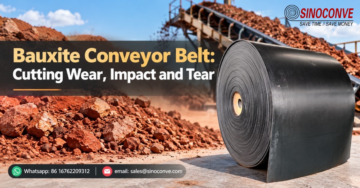
Bauxite Conveyor Belt: Cutting Wear, Impact and Tear
Suppose the removed belt has a 40 mm gouge beneath the transfer chute. Two metres away, the original cover thickness is still there. That is the clue to follow. A better abrasion number on the replacement may leave the gouge exactly where it was.
Ask for the failed section, a load-point drawing and a photograph of the largest lump with a scale. The loading-zone drawing is the first page I want in the enquiry. A clay coating on Monday and screen oversize on Tuesday can produce very different marks on the same belt. The conveying solutions for mining guide deals with the whole route. This one starts at the scar on the rubber.

01Locate the Damage
Lay the belt out with its running direction marked. A photograph taken at removal is useful only if somebody notes where the photographed patch sat relative to the chute, skirt and head pulley. Check the bottom cover too. A row of punctures on the return face can come from material caught at a pulley rather than from the ore landing above.
| What you find | Where to look next | What a cover upgrade would miss |
|---|---|---|
| Even thinning along the carry path | Abrasion, feed spread and cleaner pressure | A misadjusted cleaner |
| Cratered strip at first contact | Chute trajectory and impact support | Repeated unsupported strikes |
| Bright groove near a skirt | Packed fines or seal bearing too hard | Entrapment at the seal |
| One edge polished and frayed | Off-centre feed, frame contact, pulley deposit | The tracking cause |
| Long split starting at a fixed machine point | Tramp object and rip origin | The object that remained trapped |
| Splice edges lifting | Joint record, tension and pulley flexure | A failing joint procedure |
A tail pulley caked with clay can push the belt toward the frame. In that case, photograph the pulley as well as the rubbed edge; the edge tells only the last part of the story. Do this before cleaning the pulley.
02What “Abrasion Resistant” Measures
An abrasion test can rank compounds for a specified rubbing action. It cannot recreate an angular lump falling through a chute. If the whole cover has worn evenly, the test result is relevant. If cuts appear while most of the cover stays intact, ask about cut and gouge performance and the particular loading point. The cover grade comparison for rubber belts describes available grades; the damage map decides which property to emphasize.
A hardness reading answers how deeply the durometer indents the cover. That reading says nothing about the next angular piece. I would put tear and elongation values alongside the abrasion test method and the actual top-cover gauge. A thicker cover buys depth before a cut reaches fabric. It cannot stop the first cut, and its added thickness needs a pulley-bending check.
The boundary between a belt question and a chute question is plain on the removed belt. A short zone of torn cover under the falling stream calls for a transfer review. A broad band of slowly thinning rubber invites a cover comparison. A polished score at the steel lip sends you back to the lip. Once that contact is cleared, the abrasion-resistant belt comparison for quarry and aggregate work is a useful catalogue of cover alternatives.
03Write Down the Feed, Not the Ore Label
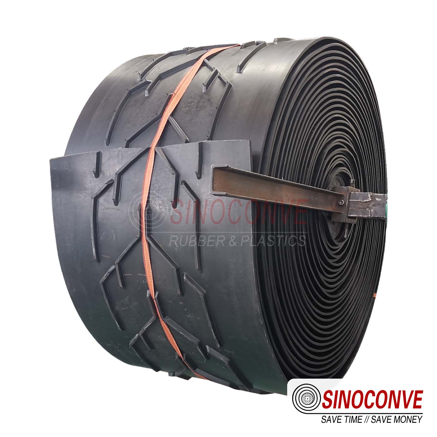
“Lateritic” and “sedimentary” are helpful words for a geologist. On a belt tender I would replace them with a sieve curve, an actual top lump and wet-season observations. The crusher and screen alter the grading; rain alters what sticks. Neither change appears in the ore name.
Sample or observe the material at the belt feed. Record the size distribution, the largest credible piece, bulk density across the expected moisture range and the wettest feed that must pass without bridging. Note screen bypasses and surges separately. A crusher setting is not a measured top size. For mixed-source ore, write down both ends of the duty, rather than averaging a wet source and a coarse one into a material that never exists.
| Feed at the chute | Belt exposure | Inspection priority |
|---|---|---|
| Coarse angular lumps | Cuts and impact concentrated at landing | Cover pits and support position |
| Clay-rich wet fines | Carryback and packing at skirts | Return idlers and seals |
| Fines plus occasional oversize | Routine deposition interrupted by severe strikes | Chute clearance after surges |
| Dry fine fraction | Distributed wear and dust | Cover loss and containment |
Copper concentrate may bring a much finer, wetter load and different chemistry. If the same conveyor alternates between it and bauxite, get samples of both and spell out cleanout between campaigns. One label, “ore,” conceals that change.
04Stand Under the Transfer Drawing
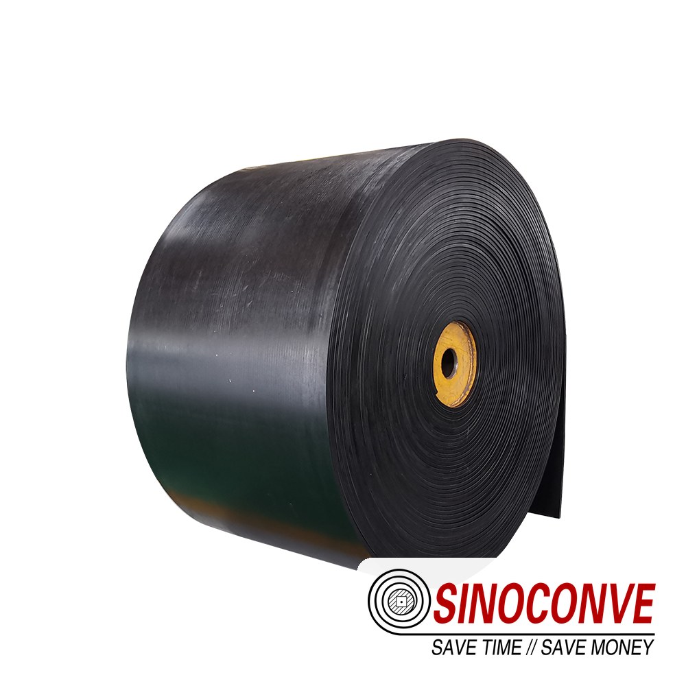
Look at the actual first contact point of the stream. Is there an impact bar or idler directly beneath it? Does the material land on a trough transition instead? A device fitted one frame downstream protects the wrong part of the belt. Metso’s loading-system descriptions include cradles and impact bars at the transfer; position matters as much as the catalogue choice.
Shortening an uncontrolled fall reduces impact energy. A retained bed of ore can take the strike in a free-flowing chute, but sticky fines may bridge a rock box. Check the wet-season material before choosing that geometry. A controlled discharge should put material near the belt centre and limit the speed difference at landing. It also needs enough clearance for the top lump and surges. Put both operating cases on the drawing.
Continuous support can help keep the skirt sealing profile stable; impact idlers may suit a different load and speed. Ask the equipment designer to show support length, deflection, replacement access and transitions. The impact bed guide compares bars and rollers. Then inspect the skirt in operation. A narrow polished line beneath the skirt tells you fines are being held there. A guide rail that works hard to centre the belt deserves a check of the feed trajectory, pulley face and structure. Idler details can be coordinated with the equipment supplier using the roller selection guide.
05A Rip Starts at a Place
An oversize stone can puncture a cover. A tooth, bolt or plate trapped beside the running belt can keep cutting for hundreds of metres. They call for different controls. Find the first centimetre of the rip. What can catch a piece of steel at that position? A stronger edge fitted while the skirt still traps scrap may simply postpone the same stop.
A practical bid comparison has two lines: the ordinary carcass and, where the incoming material justifies it, one with a breaker or rip-resisting feature. Each line needs a tension rating, allowable pulleys, joint detail and repair method. EP fabric and steel cord options cannot share one splice note. Neither choice follows a fixed conveyor-length threshold. The EP fabric carcass belt and steel cord belt pages show the constructions; the project calculation has to select among them.
For a long flight, mark every rip-sensing point on the drawing and calculate how far the belt moves between detection and standstill. Wire the required response as a trip. Put a trip test in the commissioning sheet and repeat it after controls work. Someone still needs to reach the loading skirt to remove the object.
06Wet Season: Follow the Return Side
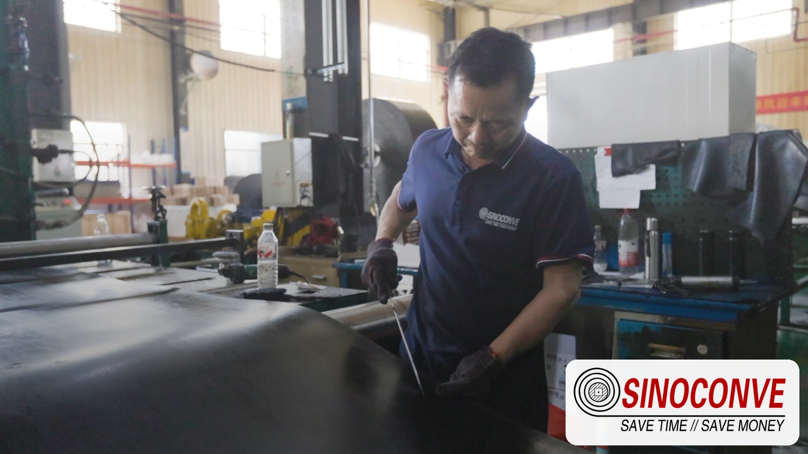
The carrying face can look serviceable while clay is accumulating on return idlers. Follow the return run to the tail. Deposits on a pulley change the belt path, and the resulting edge contact is then mistaken for a weak belt edge. At a cut or exposed fabric edge, water and fines also have a route into the carcass.
Check primary cleaner contact at the head and the path by which removed ore leaves. If removing a guard to reach the second blade takes most of a shift, its setting will rarely be checked. Before adding spray water, collect a weighed sample of return-side deposit on two comparable runs. Watch the drain for a new clay blockage.
At the port, inspect the tower floor after rain. Then look at the spare roll: it should sit dry and be stored within the maker’s limits, ready for the next planned stop. The terminal and ship-loading conveyor systems page covers the larger route; the transfer and return run decide much of the local belt life.
07What Goes on the RFQ
A width and a purchase quantity are enough for a budget number, but not for a belt comparison. Send each the material conditions and the damaged belt photographs. Ask them to state any assumption and price the proposed construction against it.
| RFQ line | Value or evidence to provide | Decision affected |
|---|---|---|
| Ore | Grading, credible oversize, moisture, density and fines | Cover and impact duty |
| Conveyor | Width, speed, route, lift, trough and every pulley diameter | Strength, bending and splice |
| Feed | Normal and surge tonnes per hour; starting and stopping | Peak tension and loading |
| Transfer | Chute drawing, real landing point, drop and support | Cover thickness and load-zone work |
| History | Dated photos with position, life and rip origin | Root-cause comparison |
| Protection | Metal control, cleaning, drainage, tracking and rip trip | Residual failure exposure |
| Installation | Roll size, access, press position and shutdown window | Joint plan and field cost |
Require the top and bottom covers, compound data with test methods, carcass rating, minimum recommended pulley diameters, splice design and field acceptance criteria in the returned quotation. List the breaker or rip-resistant option separately. The conveyor belt manufacturer and belt factory pages show product scope, but an item described only as “heavy duty abrasion resistant” is still too vague to compare.
For the splice, obtain the approved procedure and kit, press conditions, technician record and joint location. Site access may dictate the workable position. Mark each joint on the route and record repairs. Give the splice an identifier on the route drawing. See the conveyor belt splicing methods guide for joint choices.
08Frequently Asked Questions
When does a standard abrasion cover suffice?
It may be when loss is broad and even and the load point is controlled. Local craters and cuts call for the chute, support and cut duty to be reviewed as well.
Does every bauxite line need a rip-resistant carcass?
No. Compare the probability and consequence of tramp objects with the cost and performance of the proposed construction. A rip detector and foreign-object controls may also be justified.
What should we do about wet, sticky ore?
Inspect the head cleaner, return side, tail pulley and drainage under a representative wet feed. Test any added water before specifying a spray system.
What protects a belt under a high drop?
Find where the stream lands, reduce uncontrolled fall where feasible and support the belt beneath that position. Check the chute with the largest and wettest expected feed.
What if the line alternates between bauxite and concentrate?
Put both material samples on the specification sheet, along with cleanout and chemical exposure. Check transfer and cleaner performance in each campaign, not only belt tensile rating.
How should we accept a long-flight splice?
Use the procedure approved for its carcass and tension. Record materials, press settings, position and inspection results; inspect for edge lifting and separation in service.
Related Products You May Need
- Rubber conveyor belt for abrasive bulk ore
- EP fabric carcass belt for long mine flights
- Steel cord belt for high tension haulage
- Full belt catalogue by construction and width
Related Blog Posts
- Conveying solutions for mining, from pit boundary to stockpile
- Abrasion resistant belts for quarry and aggregate duty
- Heavy duty rubber belts in mining material handling
- Port conveyor belts, steep transfers and terminal selection
- Conveyor belt splicing methods and field practice