
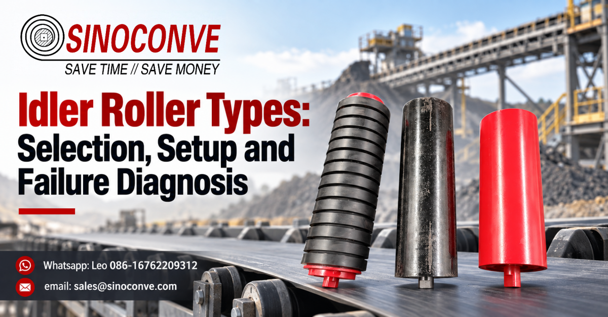
Idler roller types are decided by position and duty, not by preference, and the four numbers below are the ones we install to. Carry idlers sit every 1.0 to 1.5 m along the carrying run. Return idlers sit every 2.5 to 3.0 m underneath it. Impact idlers belong at every loading point. Self-aligning idlers belong roughly every 30 to 50 m and immediately after each curve. Get those four positions right and most roller arguments are settled before anyone opens a price list.
Now the counter-rule we repeat on every survey. A wandering belt is usually a failed roller or a seized bearing, not the wrong roller type. We have watched maintenance crews swap carrying idlers for training idlers to cure tracking drift, and the belt kept running off because one stiff return roller eight metres upstream was the real fault. Diagnose the roller before you re-type the line.
This page is built as the set of documents we carry on surveys. There is a type map that ties position to duty, a type comparison table, a spacing table with a worked example at 2.5 m/s and 1.4 t/m3, a load-per-station calculation you can copy, a selection matrix by duty, a failure diagnosis chart, and a short test for separating roller failure from belt mistracking.

One boundary before the tables start. This article is about roller type taxonomy: how the types differ in construction, what each one is there to solve, where it goes, how far apart it goes, how to pick between them, and how to read the failure. If your question is about auditing a roller supplier, drawing control or what to write in an RFQ, that belongs on the sourcing side of the business and we leave it there.
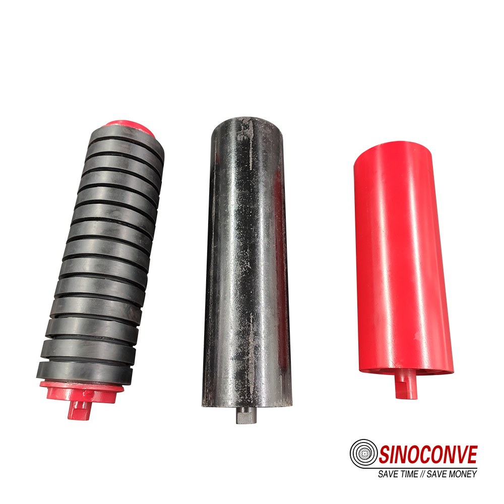
Carry, return and impact rollers from the same frame batch. The shell diameters look similar; the duty and the mounting do not.
01Why Roller Type Is a Position Decision
A roller has no personality and no brand loyalty. It is a shell, a shaft, two bearings and a seal arrangement, and the only thing that changes between a carry idler and an impact idler is which loads and which contaminants it has to survive. That is why we always start from the position on the conveyor rather than from a catalogue family. Position defines load, load defines the shell and the bearing, and the environment defines the seal. Type is the label that falls out of that sequence.
The single question that settles roller type
Ask what the roller must do at that point on the line, in one sentence. Under the belt carrying 1.4 t/m3 of crushed limestone, the answer is "support a moving load quietly". At the chute, it is "absorb an impact without deforming". On the return strand, it is "carry almost nothing and stay clean enough that the belt tracks". On a long straight run with a persistent drift, it is "push the belt back to centre". Four sentences, four types, and no overlap.
We have used that same sentence test with a conveyor roller and pulley supplier project team and with a single-plant maintenance fitter, and it holds at both scales. If you want the wider family view first, the general article on conveyor roller types and load ratings covers shell materials and ratings without going into the position logic, while this page stays with type, spacing and diagnosis.
Type map by position
The table below is the map we sketch on the whiteboard before a survey. Diameters are the working ranges we normally quote for bulk conveyors; a project can sit outside them, but the spacing rules and the load check get stricter as you move toward the ends of each range.
| Position | Duty | Roller Type | Typical Diameter | Notes |
|---|---|---|---|---|
| Carrying run, straight | Support moving load | Troughing carry idler, 3 or 5 roll | 89 to 159 mm | Most of the idler population on any conveyor |
| Carrying run at chute | Absorb impact, protect belt | Impact idler with rubber rings | 133 to 194 mm | Extend the frame 1 to 2 roller stations beyond the chute |
| Return run, general | Carry the empty strand, shed fines | Flat, V-return or spiral return | 89 to 133 mm | Spiral only where carryback is the real problem |
| Long straight runs, drifting belt | Return belt to centre | Self-aligning training idler | 108 to 159 mm | Never a substitute for alignment and pulley squareness |
| Either side of a pulley | Gradual troughing change | Transition idler, reduced angle | 108 to 159 mm | Protects belt edges from being folded at the pulley |
Two standards are worth naming when you write the layout down. ISO 1537 covers idler dimensions and arrangement for troughed belt conveyors within its scope, and ISO 5048 covers the power and tensile-force calculations for belt conveyors with carrying idlers. Neither tells you which type to use, but both set the vocabulary that a conveyor design review will expect to see. Where a fixed belt tension is already running on a heavy plant, our own starting point for the belt itself is usually an EP or steel cord rubber conveyor belt, because the roller load calculation depends on the belt mass per metre as much as on the material.
02Carry Idlers: The Workhorse of the Carrying Run
Carry idlers are 70 to 85 percent of the roller count on a typical bulk conveyor, so they carry the maintenance budget too. A three-roll troughed set is the default. The centre roll takes the load at the deepest point of the trough, and the two wing rolls hold the shoulders of the belt at the trough angle. A five-roll set divides the same belt width into shallower angles and spreads the load across more bearings, which helps on wide belts and on coarse, sharp material.
Trough angle decides the load, not the shell
This is the point that surprises people. Increasing the trough angle from 20 to 35 degrees raises the carried cross-section of a 1,200 mm belt by a large margin, and it also changes how much of the material weight lands on the centre roll relative to the wings. On a three-roll set at 35 degrees, the centre roll ends up with well over half the vertical load. That is why a plant that raises trough angle to stop spillage, without touching roller spacing or shell thickness, starts denting centre rolls instead of spilling.
If you are still choosing between the carrying-run rollers themselves, our conveyor roller range lists the shell and bearing combinations we build most often, and the practical selection walk-through in the conveyor idler roller guide covers diameter, shaft ends and frame fits in the order a buyer meets them.
Carry idler register
| Structure | Shell Diameter | Typical Trough Angle | Where It Belongs | Watch Out For |
|---|---|---|---|---|
| 3-roll troughing set | 89 to 133 mm | 20 to 35 degrees | Standard aggregate and quarry lines | Centre roll overload when trough angle is raised late |
| 5-roll troughing set | 108 to 159 mm | 35 to 45 degrees | Wide belts, high capacity, coarse rock | Two more bearings per station to grease and monitor |
| Single flat carry roll | 89 to 108 mm | Flat | Belt feeders, weigh bridges, short belts | Almost no load capacity; do not use on bulk incline |
| Suspended / garland set | 89 to 133 mm | 30 to 45 degrees | Unstable ground, portable crushing spreads | Rope tension must be re-set as the chain wears |
| Composite shell carry roll | 89 to 133 mm | 20 to 35 degrees | Wet, saline or chemically active sites | Lower stiffness; check load rating before substituting |
On the belt side of the same station, carry geometry only works if the belt has the transverse stiffness to hold the trough. A limp belt sags between idlers no matter what roller you fit under it, and coarse material will then sit in the sag and shake. On a stone line we normally expect the belt carcass to be chosen together with the idler spacing rather than after it, which is why we quote the industrial conveyor belt for a crushing circuit against the idler layout the customer already has.
03Return Idlers: Keeping the Return Run Clean
The return strand supports almost no material weight, which is exactly why it is neglected. A return idler at 2.5 m spacing on a 1,200 mm belt carries a few kilos of belt and whatever has stuck to the cover. Then a chunk of wet clay dries on the pulley, passes under a flat return roller, and either the roller stalls or the belt is lifted off centre. Most of the tracking complaints we are called to investigate start on the return run, not the carrying run.
Flat, V-return or spiral: three jobs, not three grades
A flat return roller is the cheapest way to hold the strand up and it is correct on clean, dry, well-scraped belts. A V-return set, two rolls angled at about 10 degrees to form a shallow V, uses the belt's own tension to keep it centred and is the better choice where small amounts of material fall on the return strand. A spiral return roller replaces the smooth shell with a helical winding that lets fines fall through the gaps instead of building a ridge of compacted material on top of the roller.
Return-side hardware also has to survive the environment with less attention than it deserves. On heavy, wet and abrasive return runs we normally go to closed-end steel conveyor rollers with a labyrinth path rated for the dust actually present, because an open bearing under a return strand fills with fines within one shift. If the belt itself is being replaced at the same time, the cover grade matters as much as the roller: a conveyor belt supplier can match cover hardness to the scraping regime, and a harder cover sheds less.
Return idler register
| Type | Typical Spacing | Cleaning Effect | Maintenance Character |
|---|---|---|---|
| Flat return roller | 2.5 to 3.0 m | None | Simple, cheap, easy to replace |
| V-return set, 10 degrees | 3.0 m | Self-centring, sheds small lumps | Two bearings per station |
| Spiral return roller | 2.5 to 3.0 m | Continuous self-cleaning by geometry | Noisier; check for wrap on stringy loads |
| Rubber-disc return roller | 2.5 to 3.0 m | Breaks and sheds sticky fines | Check disc wear, not shell roundness |
| Return roller with rubber rings | 3.0 m | Limited; mostly protects the belt | Ring creep and hardening under heat |
04Impact Idlers at Loading Zones
Everything arriving at a conveyor arrives through a chute, and everything that leaves a chute is moving faster than the belt. The vertical component of that impact has to go somewhere. If the belt cover absorbs all of it, the cover bruises, the carcass fatigues, and the belt fails at the loading point long before the rest of the run is worn out. Impact idlers exist to take that energy into rubber instead.
How impact idlers differ from carry idlers
The structure is a heavier shaft and a set of rubber discs or rings moulded onto the shell, spaced along the roller so the belt touches rubber rather than steel. The rings compress under impact and recover, which spreads the peak force over a longer time and a wider area. There is also a height effect: an impact idler set is usually mounted so its top face sits at or slightly above the belt line, giving the cover a controlled cushion rather than a rigid anvil.
On site, the classic error is a single impact station directly under the chute centre with ordinary troughing idlers immediately either side. The belt gets a soft landing and then a hard line of contact two metres later, and it cracks along that line. Extend the impact zone one to two stations beyond the chute in both directions, and use graduated trough angles as you come out of it.
Impact idler layout notes
| Parameter | Typical Value | Why It Matters |
|---|---|---|
| Ring hardness | 60 to 75 Shore A | Softer absorbs more; harder resists cutting on sharp rock |
| Cushion height above belt line | 0 to 5 mm | Too high lifts the belt off adjacent stations and re-loads them |
| Spacing inside the chute zone | 0.4 to 0.6 m | Closer centres stop the belt bridging between stations |
| Zone length beyond chute | 2 to 4 m | Material is still bouncing when it leaves the chute mouth |
| Roller shaft diameter | 25 to 40 mm | Impact load bends undersized shafts before the rings wear |
We quote rubber-ring impact sets for aggregate, clinker and ore loading, and the impact roller supplier notes on loading-zone arrangement go into the frame dimensions in more detail. Pair them with a belt cover rated for the same abrasion class, which on a stone line generally means a DIN 53516 abrasion loss of 90 to 150 mm3 rather than the 250 mm3 used on lighter duties.
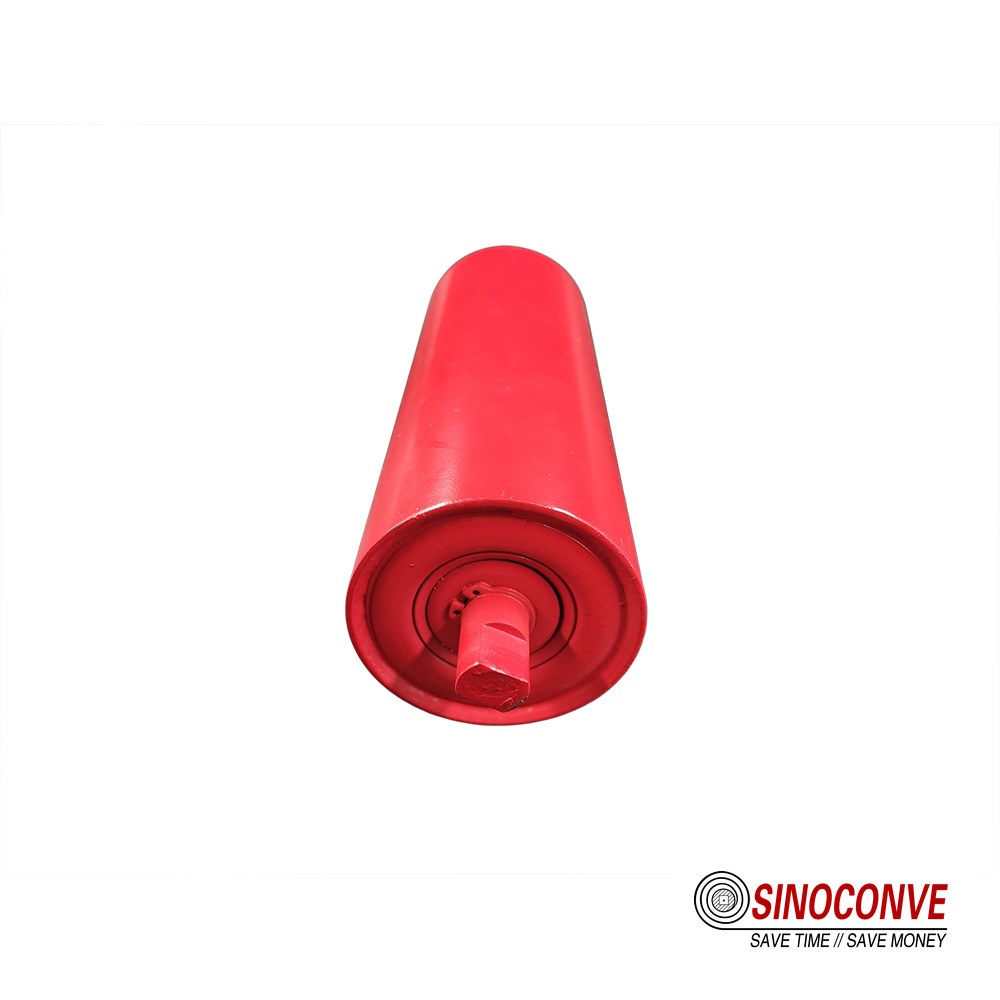
Rubber-ring impact idlers in the loading zone, with the cushion set just above the belt line.
05Self-Aligning and Training Idlers
A self-aligning idler is a corrective device, and like every corrective device it should be the last few percent of the tracking system, not the whole of it. Its job is to detect a small lateral displacement of the belt and convert it into a steering force. It cannot detect a bent frame, a seized return roller or a pulley that is out of square, and if you ask it to, it will simply fight the belt harder and wear the edges.
Two mechanisms worth knowing
The common design mounts the troughing rolls on a rotating frame carried on a central pivot. When the belt drifts toward one side, the increased friction on that side of the rolls turns the frame slightly, and the angled rolls then steer the belt back toward the centre. A second family uses side guide rollers or a vertical pivot with a leading roll, where the belt edge itself contacts a roller and the reaction swings the assembly. Both work. Neither works when the pivot is packed with fines and can no longer move.
Field note from our engineers: A cement plant line kept drifting over a 60 m straight run and the first report said the idler type was wrong. We measured three return rollers in that stretch: two turned freely and one needed noticeably more torque to rotate by hand. It was a dried-clinker-seized bearing. All three were replaced, the frame was re-levelled, and the vertical offset between adjacent stations came down to under 2 mm. The drift stopped that afternoon, with no change of roller type anywhere on the conveyor.
Training idlers are also the component most often blamed for edge wear that was present before they were installed. If the belt has been running off for months, the edges are already feathered and the cover is already thinned. In that case the training idler will hold the belt but the damage keeps travelling. This is the point at which we ask a plant to check the whole tracking chain, including belt squareness, pulley alignment and load placement, rather than adding a fourth training idler to the same run. For the belt-side view of that chain, the case that a conveyor belt manufacturer usually makes is that a square belt on a square frame needs very little steering hardware at all.
Training idler spacing and mounting
| Location | Spacing / Offset | Mounting Note |
|---|---|---|
| Long straight carrying run | Every 30 to 50 m | Pivot axis must be vertical and free of packed dust |
| After each vertical curve | One station, 3 to 5 m downstream | Not on the curve itself |
| After the loading point | One station, 5 to 8 m downstream | Material placement is a common drift cause |
| Approach to head and tail pulley | 10 to 15 m before the pulley | Closer than this fights the trough transition |
| Return strand, long runs | Every 40 to 60 m | Return-side training is often more effective than carrying-side |
For the wider picture of how a self-aligning frame is chosen and installed, our article on the self aligning roller works through frame types and selection, and it is the right next read if you are specifying one for a new conveyor rather than fixing an old one.
06Transition Idlers: Managing the Curve
At the head pulley the belt has to change from a 35 degree trough into a flat wrap around the drum. If that change happens in one step, the belt edge is stretched and the centre is compressed, and on a belt with a stiff carcass the edge will start to wrinkle or crack inward from the shoulder. Transition idlers exist to make the change gradual, over a defined distance, with a controlled sequence of trough angles.
How the sequence is built
The usual arrangement is three or four stations between the last full-trough carry idler and the pulley, with the trough angle reduced at each step, and with the stations closer together than normal carry spacing. On a 1,200 mm belt with a 35 degree main trough, we typically see something like 35 degrees, then 25, then 15, then 5, spread over 3 to 5 m, with the final station 0.8 to 1.2 m from the pulley face. The exact numbers belong to the belt construction: a thick steel cord belt tolerates less edge strain than a thin EP belt, so it needs a longer transition.
Two failure patterns tell you the transition is wrong. Edge buckling or a wave along the belt shoulder within 3 m of the pulley usually means the transition is too short. Roller shells wearing in a narrow band, with the rest of the shell untouched, usually means a step change in trough angle is loading one station far more than its neighbours. Both are geometry faults, and neither is cured by changing roller type.
The third input is belt tension. A transition that is geometrically acceptable under light tension can still damage the edge at full tension, because the edge strain scales with the tension. If the plant is running a conveyor rollers for belt systems upgrade and raising capacity at the same time, the transition length should be re-checked against the new tension rather than inherited from the old drawing. It is also worth remembering that the same plant usually has a transmission belt manufacturer relationship with us for its crusher and fan drives, and the same tension logic applies on those shorter, faster drives.
Transition idler register
| Arrangement | Trough Angle Steps | Typical Transition Length | Used On |
|---|---|---|---|
| 3-station transition | 35, 20, 5 degrees | 3.0 to 5.0 m | Belt widths to 1,200 mm, EP carcass |
| 4-station transition | 35, 25, 15, 5 degrees | 5.0 to 8.0 m | Wide belts, steel cord, high tension |
| Single adjustable station | Variable | 1.5 to 2.5 m | Retrofit and field correction |
| Transition on return side | Flat to V-return | 2 stations | Belts with edge damage history |
07Spiral and Rubber-Disc Idlers
There is a family of rollers that does its cleaning work through shape rather than through a scraper blade. Nobody has to adjust them, nobody has to set a blade gap, and they never score the belt cover. The trade-off is that they clean only what falls into their path, and they cannot remove anything that has bonded to the cover.
Spiral rollers: the geometry does the work
A spiral roller is a smooth shaft with a helical winding wound onto it, usually in a continuous bar or in sections with a left-hand and right-hand lead from the centre. The winding touches the belt on a narrow contact line and leaves open gaps between turns. Fine material that drops out of the belt lands in those gaps, falls through to the ground, and never builds a ridge. The helix angle means the winding also nudges material outward toward the belt edges rather than letting it compact in the middle.
Rubber-disc rollers: breaking the bond
A disc roller carries a series of rubber or polyurethane discs on a steel shaft, each disc angled or flat, with gaps between them. The belt rides on the disc rims. As the belt passes, each disc compresses slightly and then releases, and that repeated local deflection breaks the adhesion of wet or sticky fines. The material drops into the gaps and falls away. On wet coal, wet limestone and clay-carrying circuits, disc rollers remove material that a flat roller would simply roll into a hard layer.
Both families live on the return strand, and both are frequently deployed as a second line of defence behind a primary cleaner. What they cannot do is replace the primary cleaning stage. A roll that carries a ten millimetre bonded layer of clay under it will keep carrying it whatever the shape of the roller, because the layer is bonded to the cover, not resting on it. If you are choosing between blade-based and geometry-based cleaning, our article on conveyor belt cleaning methods sets out which jobs each one can and cannot do, and the role of a conveyor belt cleaner at the head pulley is covered there in detail.
| Type | Structure | Problem It Solves | Position | Failure Risk |
|---|---|---|---|---|
| Spiral return roller | Helical winding on a steel shaft | Fine dry material building a ridge on the return strand | Return run, behind the primary cleaner | Winding jam on large lumps; wrap on fibrous loads |
| Rubber-disc return roller | Steel shaft with flexible discs | Wet or sticky fines bonding to the cover | Return run, wet and clay-carrying circuits | Disc wear and hardening; misalignment between discs |
| Rubber-ring impact idler | Rings moulded on a heavy shell | Impact energy at the loading point | Carrying run under the chute | Ring cut on sharp material; shaft bend |
| Smooth flat return roller | Plain steel or polymer shell | Nothing beyond supporting the strand | Return run, clean and dry belts | Build-up under the shell on sticky loads |
08Disc Return Rollers vs Flat Return
The comparison that matters
A flat return roller supports the belt over a continuous line of contact. Anything lying on the return cover is trapped between the belt and the shell and is rolled smooth. If that material is dry and loose, it simply falls off at the next station and there is no problem. If it is wet and sticky, it consolidates into a hard band, the roller diameter effectively grows, and the belt is lifted unevenly and starts to steer. A disc roller interrupts that contact. Each disc presses and releases, and the material is dropped before it can be consolidated.
| Criterion | Flat Return Roller | Disc Return Roller |
|---|---|---|
| Contact with the belt | Continuous line, full width | Intermittent, disc rims only |
| Behaviour on sticky fines | Consolidates into a hard band | Breaks the bond and sheds material |
| Behaviour on dry clean belts | Correct and lowest cost | No benefit, higher cost and noise |
| Effect on belt tracking | Build-up changes effective diameter and steers the belt | More stable where build-up was the cause of drift |
| Inspection item | Shell roundness and bearing free rotation | Disc wear, disc-to-disc alignment, gap blockage |
| Relative first cost | Baseline | Typically two to four times the flat roller for the same shaft |
Where plants run mixed duties on one site, the practical compromise we suggest is disc rollers in the wet section and flat rollers after the drying or screening stage. Set the changeover at a transfer point so that the maintenance team can see the boundary in the drawing. If the plant also drives its screens and fans from belt drives, the same incremental thinking applies on those drives, which is why a V-belt manufacturer conversation usually starts with where the wear actually occurs rather than with the whole machine.
09Bearing and Seal Types by Environment
What the environment actually does
Fine dust does not care about bearing clearances. It enters through the smallest path available, mixes with grease, forms an abrasive paste, and turns a smooth raceway into a scored one. Water does the opposite: it washes grease out, leaving metal on metal, and it corrodes the ball and the raceway. Heat shortens grease life and softens seals, which then leak and admit the dust they were meant to exclude. In a port or a quarry you often get all three at once.
The countermeasure is the seal arrangement rather than the bearing size. A labyrinth seal with several changes of direction and a grease-filled chamber is the standard answer for fine dust because the dust has to travel a long path in a still pocket of grease. A contact lip seal excludes water better but adds drag and wears the shaft. Deep-groove ball bearings are normal for light and medium duty, while heavier duties use higher-capacity arrangements or tapered roller bearings where the design allows it. Double-row and self-aligning types appear in applications where frame deflection is expected, most often on long spans and portable equipment.
Sealing is only half of it. Regreasing intervals, grease type and grease quantity are the other half, and they change with environment. A sealed-for-life roller that is not regreased suits a clean plant. A dusty quarry usually needs a regreasable design with a defined interval in the maintenance plan. Our own sealed conveyor roller note covers labyrinth and grease-chamber design for fine dust, and the same logic is extended to salt air and acid wash zones in the material on the corrosion resistant conveyor roller page.
| Environment | Bearing Arrangement | Seal Choice | Maintenance Implication |
|---|---|---|---|
| Clean, dry, indoor | Deep-groove ball, single row | Contact seal or sealed-for-life | Replace on failure; no grease route needed |
| Fine dust, dry | Deep-groove ball, C3 clearance | Multi-path labyrinth with grease chamber | Regrease on a fixed interval; watch for paste formation |
| Wet and washdown | Deep-groove ball, stainless option | Labyrinth plus lip seal, water-resistant grease | Shorter grease interval; check for emulsion |
| Salt air, port and coastal | Stainless or coated bearing seat | Labyrinth with corrosion-protected housing | Inspect housing and shaft ends, not only the bearing |
| High ambient, above 60 C | Higher-clearance ball or roller | Heat-stable seal compound | High-temperature grease; shorter relube cycle |
| High load, shock present | Heavy-duty ball or tapered roller | Labyrinth with reinforced housing | Check shaft deflection as well as the bearing |
One practical note on volume. Rollers are consumed in quantity, and a plant that standardises on one or two designs will always get better service than one that holds eleven variants. Standardisation is a legitimate reason to buy in volume, and we supply wholesale conveyor belts and roller ranges on that basis, but the standard design still has to be the right one for the dustiest and wettest position on the site, not the average position.
10Spacing Rules: Carry, Return and Loading
Worked example: 1.4 t/m3 at 2.5 m/s
Take a 1,000 mm belt carrying crushed limestone at 1.4 t/m3 on a 2.5 m/s line, 3-roll troughing at 35 degrees. A commonly used rule is that the sag between carry idlers should stay within about 2 percent of the spacing. At 1.2 m spacing that allowance is 24 mm, which is comfortable. Move to 1.5 m and the allowance rises to 30 mm, but the taller dip collects material at the loading end and the belt starts slapping at the first station after the chute. Move to 1.8 m and the same belt visibly sags at 2.5 m/s and throws material at the transfer.
Field note from our engineers: A quarry line was running carry idlers at 1.8 m on a 1,000 mm belt with 1.4 t/m3 stone at 2.5 m/s, and the complaint was a permanent spillage band under the second half of the conveyor. We measured the sag, then re-spaced the carry idlers to 1.2 m over the loaded section only, leaving the loading zone and the transition untouched. Sag and spillage both came down, and the drive current dropped slightly because the belt was no longer being lifted out of a dip at every station.
Spacing table with reasons
| Run | Belt Speed | Material Density | Spacing | Reason |
|---|---|---|---|---|
| Carry, general | 2.5 m/s | 1.4 t/m3 | 1.2 m | Keeps sag inside the 2 percent allowance |
| Carry, heavy ore | 2.0 m/s | 2.2 t/m3 | 0.9 to 1.0 m | Higher density adds mass per metre directly |
| Carry, light product | 3.0 m/s | 0.8 t/m3 | 1.4 to 1.5 m | Lower mass per metre allows wider centres |
| Loading zone | Any | Any | 0.4 to 0.6 m | Prevents the belt bridging between stations under impact |
| Return, general | 2.5 m/s | 1.4 t/m3 | 2.5 to 3.0 m | Only belt mass to support; sag tolerance is larger |
| Transition to pulley | Any | Any | 0.8 to 1.2 m | Controls edge strain as the trough opens flat |
Dust makes spacing slightly harder to hold, because a station that is buried in fines cannot be inspected and its spacing will drift as the frame is disturbed. On a dusty site, sealing the roller and keeping the frame clear is worth more than a textbook spacing number. The dust resistant conveyor belt work we do on the belt side follows the same principle, and if you want the wider industry view of how spacing and duty interact at a mine or quarry, our mining and quarrying pages collect the application notes.
11Load per Roller Station
Worked calculation
| Input | Value | Step | Result |
|---|---|---|---|
| Capacity and speed | 600 t/h at 2.5 m/s | 600 / (3.6 x 2.5) | 66.7 kg of material per metre |
| Belt mass | EP 630, 1,000 mm, 4 ply | From belt data sheet | about 18 kg per metre |
| Combined moving mass | 66.7 + 18 | Add both | 84.7 kg per metre |
| Vertical load per station | 84.7 x 1.2 m spacing | Multiply | 102 kg, about 1.0 kN |
| Split across 3 rolls at 35 degrees | Centre about 0.63, each wing about 0.32 | Typical distribution | Centre 64 kg, wings 33 kg each |
| Service factor | 1.5 for uneven feed and lumps | Apply to centre roll | Design load about 96 kg, say 1.0 kN |
Two things go wrong with this calculation in practice. The first is using the nominal capacity when the belt is often run 20 percent above it. The second is ignoring the fact that the roll that matters is the one at the discharge or the one just after the loading point, where the load is not yet settled. Rotating speed is the third factor: at smaller shell diameters the bearing turns faster for the same belt speed, and bearing life falls with roughly the third power of load and the cube of speed. This is the argument set out in more depth in our note on steel conveyor belt roller performance, and it is why we rarely recommend dropping below 89 mm shell diameter on a fast, heavy line.
Once the load is known, the belt choice usually follows it. On a cement or clinker circuit carrying 2.0 t/m3 or more, the load per station rises sharply for the same spacing, and the belt cover also has to survive the temperature. The cement conveyor belt selection material covers that combination, and the same load arithmetic applies with a higher density figure.
12Selection Criteria Matrix by Duty
Matrix by duty and environment
| Condition | Primary Criterion | Recommended Type | Reject If |
|---|---|---|---|
| Clean indoor line, light product | Cost and quiet running | Sealed flat carry and flat return | Heavy shell quoted for no reason |
| High drop, coarse rock | Impact energy | Rubber-ring impact idlers, close centres | Standard carry idlers inside the chute zone |
| Fine dry dust, no washdown | Sealing path | Labyrinth seal with grease chamber | Open bearings with a single felt washer |
| Wet, sticky, high carryback | Self-cleaning geometry | Disc or spiral return rollers | Flat return rollers alone in the wet section |
| Persistent drift on a long run | Tracking correction | Self-aligning idlers at 30 to 50 m | Training idlers used instead of alignment |
| Wide belt, high tension, steel cord | Edge strain | 4-station transition, long and gradual | Single step from trough to flat at the pulley |
| Coastal or acid-wash zone | Corrosion | Coated or stainless bearing seat, protected housing | Painted carbon steel housing left exposed |
If you want the same decision logic worked through from the roller side in more detail, the practical conveyor roller selection guide takes each duty in turn and asks what has to be verified before ordering. Plants that distribute across several sites usually end up standardising two or three designs for the whole group, and we support that as a conveyor belt distributor arrangement where a single specification has to travel between sites.
13Failure Diagnosis: Seizure, Flat Spots, Vibration
Rollers fail in four recognisable ways, and the way they fail tells you what to change. If you replace a failed roller with an identical one and it fails again in the same place within a year, the roller was never the fault. Look at the position, the load, the sealing and the alignment instead.
Symptom, cause and response
| Symptom | Likely Cause | Check Order | Corrective Action |
|---|---|---|---|
| Roller will not turn by hand | Bearing destroyed by water ingress or dust paste | Seal, then grease, then shaft wear | Replace and change the seal class for that position |
| Flat spot worn on one side of the shell | Stalled roller dragged by the belt | Belt tension, then roller free rotation | Replace roller; inspect neighbours in the same run |
| Pulsing vibration at speed | Out-of-round shell, bent shaft or material build-up | Shell roundness, build-up, then shaft straightness | Clean or replace; check the loading point for lumps |
| Shell worn in a narrow band only | Belt not seated in the trough; edge contact | Trough angle, frame squareness, belt edge condition | Correct the geometry rather than the roller |
| Grease weeping from the seal at rest | Over-greasing or a heat-softened seal | Temperature at the station, then grease quantity | Reduce grease volume; check the seal compound for the temperature |
| Roller shaft broken at the end | Impact load or a mis-set frame forcing the shaft | Impact zone, then frame slot condition | Heavier shaft in impact duty; repair the frame |
Where several rollers on one conveyor fail at the same station repeatedly, we treat it as a design question rather than a maintenance question. That usually means the impact zone is under-built for the lump size, or the spacing is too wide for the density, or the trough angle was raised after the rollers were purchased. Our work on conveyor rollers for mining bulk handling describes the same pattern on mine and quarry duty, and the response is the same every time: change the duty classification, not the brand.
Roller quality is worth one sentence here and no more. A plant that audits its supplier on drawings, inspection records and batch consistency will see fewer of these failures, and the right place to read about that discipline is the sourcing side rather than this page. What matters for diagnosis is that a conveyor belt factory and its roller line can tell you, from the wear pattern alone, which position on your conveyor the failed item came from.
14Roller Failure vs Belt Mistracking
The twenty-minute separation test
| Observation | Points To Roller Failure | Points To Mistracking |
|---|---|---|
| Drift appears at one place only | Yes, if a roller in that zone drags | Usually no; mistracking tends to be progressive |
| Drift direction changes with load | Rarely | Commonly; points to off-centre loading |
| Roller turns freely but belt still drifts | No | Yes; look at pulley squareness and belt squareness |
| One roller noticeably harder to turn | Yes; the classic cause of local drift | No |
| Drift reverses when the belt is run empty | Sometimes, if build-up is the cause | Yes; frame or pulley geometry |
| Belt edge worn on both sides | Unlikely on its own | Yes; the belt has been travelling off centre for months |
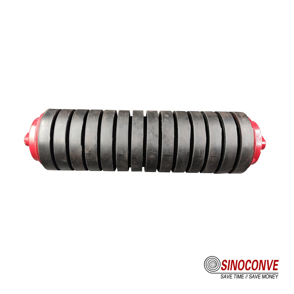
A training idler working as intended. It corrects small drift; it cannot compensate for a seized roller upstream.
Once the diagnosis is clear, the belt-side checks are the same ones set out in the EP conveyor belt tracking guide, which walks through squareness, loading position and pulley alignment in the order that finds the fault fastest. If you have read this far and still want the short version, our FAQ page collects the questions we are asked most often about rollers and tracking, and the belt construction details sit on the EP rubber conveyor belt page.
15Installation and Alignment Tolerances
Roller type and spacing are worthless if the frame is not square, and frame squareness is the cheapest thing on the list to fix. These are the tolerances we work to when we re-align a conveyor frame in the field.
| Dimension | Tolerance | Effect if Out | Method |
|---|---|---|---|
| Height of adjacent stations | 2 mm vertical | Local sag and slap, material thrown at the low point | String line and steel rule |
| Squareness to belt centreline | 1.5 mm over the station width | Continuous sideways push, edge wear on one side | Diagonal measurement across the frame |
| Frame level across the belt | 1 mm per 3 m | Trough looks correct but the belt loads one wing roll | Spirit level and shim packs |
| Pulley squareness to frame | 1 mm per metre of belt width | Belt walks toward the slack side along the whole run | Piano wire along the belt edges |
| Slot clearance in the frame | 0.5 to 1.5 mm | Shaft hammers in a loose slot and eventually breaks | Feeler gauge at the bearing housing |
Alignment work is also where most roller replacements should end. The wider specification background sits in the general conveyor roller types and load ratings article, and the product catalog lists what we hold across roller diameters and shaft ends.
16Replacement Strategy and Spares
A roller rarely fails alone. Bearing conditions are shared across a run, so a failed return roller is a signal that its neighbours are on the same clock. Replace in groups.
What to hold on site
| Item | Replacement Strategy | Stock Basis |
|---|---|---|
| Carry idlers, standard stations | Replace on failure, inspect by zone | 2 percent of installed count |
| Return rollers | Replace in blocks of five along a run | 3 percent, higher in wet sections |
| Impact idlers | Replace the whole zone at once | One full chute zone per conveyor |
| Self-aligning idlers | Rebuild pivot, do not scrap the frame | Two frames plus pivot spares |
| Bearing and seal kits | Match to the environment class | One kit per ten rollers in service |
The reason to standardise here is inspection. A plant running three roller designs can judge wear against known life, and the OEM conveyor idler manufacturer relationship behind a project order is usually what makes that standardisation possible in the first place. For roller dimensions, shafts and bearing options, our own conveyor roller range is the starting point.

17Frequently Asked Questions
How many idler roller types are there in practice?
Six position types cover almost every bulk conveyor: carry, return, impact, training, transition and the self-cleaning return family. Material variants multiply the number, but position decides which one you need.
What spacing should carry idlers have?
Start at 1.2 m for a 2.5 m/s line carrying 1.4 t/m3, then check the sag. Heavy ore at 2.2 t/m3 usually wants 0.9 to 1.0 m.
When do I need impact idlers?
Anywhere material falls onto the belt, and for 2 to 4 m past the chute mouth.
How often should self-aligning idlers be fitted?
Every 30 to 50 m on a long straight run, one after each vertical curve, and one 5 to 8 m downstream of the loading point. Reversible conveyors need the symmetric type.
Do disc return rollers replace flat return idlers?
Only in the wet or sticky section of the line. On a clean, dry, well-scraped belt the flat roller does the job at a fraction of the cost, and a disc roller simply adds noise and wear parts.
Which bearing and seal suit a dusty site?
A multi-path labyrinth seal with a grease-filled chamber, on a regreasable roller. Contact seals keep water out better but add drag, so dusty and wet sites need both.
How do I calculate load per roller station?
Add material mass per metre to belt mass per metre, multiply by the spacing, then split the total across the rolls by trough angle. Apply a service factor of about 1.5 for uneven feed and lumps.
How do I tell a failed roller from belt mistracking?
Stop the belt and turn the rollers in the drift zone by hand. One that needs noticeably more torque is your fault. If they all turn freely, the problem is geometry: pulley squareness, frame level or where the material lands.
How do transition idlers differ from carry idlers?
Lower trough angles, closer centres and a defined sequence over 3 to 8 m before the pulley. Same hardware, different duty, and a steel cord belt needs a longer transition than a thin EP belt.
18Related Products You May Need
- Conveyor rollers and idler sets in carry, return, impact and training designs.
- Rubber conveyor belts for the carrying run these rollers support.
- Heat-resistant belts for clinker and cement duty above 60 C at the station.
- Full product catalog for a single consolidated enquiry.
19Related Blog Posts
- Conveyor roller types and load ratings for shell and bearing selection.
- Self aligning roller selection when tracking correction is on the agenda.
- Impact roller supplier notes for loading zones if chute impact is the problem.
- Conveyor idler roller guide for the buying sequence from frame to order.