


On an aramid cord belt the pitch is fixed by the pulley teeth, and every other number follows from that one choice. Cord lay, tooth depth, allowable elongation, minimum pulley diameter, take-up travel, none of them can be settled before the pitch is settled. So we specify pitch first and fill in the rest afterwards. Aramid cord buys you low stretch and high strength per millimeter of belt width, yet it will not tolerate a pulley smaller than the stated minimum, and it will not tolerate back-bending. Put both limits in the RFQ and the drive stops being a gamble. What follows is a set of working documents you can carry out to the machine: a pitch register, a cord construction table, a pulley and back-bend register, and a tensioning method table.
We cut aramid cord timing belts in Ningbo for packaging, robotics, textile and light-conveying drives, and most of the failures we are asked to explain come from wrong numbers on the drawing rather than wrong rubber. A belt that is specified correctly on pitch, cord direction and minimum pulley diameter tends to run quietly for years. A belt that is specified loosely develops its first tooth crack within a few months, and the report usually blames the supplier. This page is an attempt to move that conversation one step earlier, to the design stage.

We sit on both sides of the belt business, which is useful here. The same plant that lays aramid cord into PU also presses heavy fabric carcass, so when a design engineer asks us to compare a cord timing belt with a heavy-duty rubber conveyor belt we can answer from the curing press, not from a catalog. As a conveyor belt manufacturer we run the same tension-testing bench for both product families, and the elongation numbers we quote for aramid cord are measured on that bench, on finished endless belts, not on raw cord samples.
One clarification before the tables start. This article is about pitch and carcass engineering, how the pitch is chosen, how the cord is built and laid, how the belt stretches, and how it is tensioned and inspected. If you are still deciding between an aramid cord and a steel cord carcass in the first place, that decision has its own page; we point you there once, in Section 14, and we do not repeat the comparison here.
01Pitch First: Why Pitch Governs Every Other Number
Pitch is the linear distance from the center of one tooth to the center of the next, measured on the pitch line. On a synchronous drive the pulley does not grip the belt by friction; it drives it by tooth interlock, which means the belt and the pulley must agree on the same pitch or the teeth will not seat. That single agreement cascades through the whole design. A fine pitch wraps a small pulley smoothly and gives high resolution, but each tooth carries less load. A coarse pitch carries more torque per tooth but needs a bigger pulley to wrap, and it makes the belt stiffer in back-bending. There is no way to optimize elongation, minimum pulley diameter or positioning accuracy until the pitch is on the table.
Our rule of thumb, after a lot of drive surveys, is to start from the smallest pulley the machine already has. That pulley sets a ceiling on how fine the pitch can usefully go, because a pitch that is too fine for the load spreads the torque over too little cord. Then we check the required positioning accuracy; if the axis needs to repeat inside a tenth of a millimeter, we usually stay at 5 mm or 8 mm pitch even if the load would allow 14 mm. Only after both checks do we look at belt width.
The pitch register we actually work from
The table below is the short list we keep in the quoting sheet. The pulley ranges are the ranges we normally see in industrial drives and not a hard limit; a supplier can quote outside them, but the cord stress and the back-bend check get stricter as you move toward the edges.
| Pitch | Tooth Pitch | Typical Pulley Range | Best Application | Notes |
|---|---|---|---|---|
| T2.5 | 2.5 mm | 10-40 teeth | Instrument drives, tiny axes | Low load only; aramid cord is often overkill here |
| T5 | 5 mm | 12-60 teeth | Light packaging, small servo motors | Tension evenness matters more than on T10 |
| T10 | 10 mm | 14-60 teeth | General automation, indexing tables | The workhorse; easiest to source in aramid |
| AT10 | 10 mm | 14-60 teeth | High-torque positioning, machine tools | Deeper tooth profile carries more load per tooth |
| 8M | 8 mm | 18-60 teeth | Servo axes, robotics, gantry | Round-profile tooth; quiet, but check pulley series |
| 14M | 14 mm | 22-80 teeth | Heavy transport drives, low speed | Long centre distances; watch take-up travel |
| AT20 | 20 mm | 25-100 teeth | High load, low speed, heavy indexing | Back-bend almost always prohibited at this size |
Pitch register used for aramid cord belt quoting; pulley ranges reflect industrial drives we survey, not absolute limits.
If you need the wider picture of how pitch families differ across rubber and PU constructions, the general timing belt types and pitches article covers it without going into cord engineering. And if you want to see how a finished timing belt is offered across pitches and widths, the product page lists the standard combinations we mold.
02Aramid Cord Construction: Twist, Lay and Direction
Cord is not a single filament. It is a bundle of aramid yarns twisted into plies, and the plies are twisted again into the cord, and the whole rope is then laid into the belt with a controlled tension and a controlled spacing. Each of those stages leaves a fingerprint in the finished belt. Twist level controls how the cord stretches and how it fatigues. Lay length controls how evenly the load spreads from cord to cord. Spacing controls how much rubber sits between cords, which in turn controls how well the teeth resist shearing away from the carcass.
The usual construction for a general automation belt is a two-ply cord with a moderate twist count, laid at a pitch of roughly one cord per two millimeters of width. Increase the cord count and you get more strength per millimeter, but you also reduce the rubber web between cords, and below a certain web the cord starts to chafe against its neighbour under shock load. We have opened belts that failed at 4 million cycles with the cords still intact and the web between them powdered; the cord was never the weak point.
Construction variants and what they trade
Three constructions cover most of what we ship. The table lists them with the numbers we normally quote; your application may need a different twist count, and the way to settle it is to send the duty cycle rather than the drawing alone.
| Cord | Construction | Twist Direction | Linear Density | Elongation Class |
|---|---|---|---|---|
| Standard aramid | 2-ply, medium twist | S, Z or balanced | Around 1,200-1,600 tex | Low, typically under 0.6% at working load |
| High-modulus aramid | 2-ply, low twist | Usually Z | Around 1,600-2,200 tex | Very low, but less shock-tolerant |
| Hybrid cord | Aramid plus a compliant core | Balanced | Depends on blend | Medium; softer on small pulleys |
A note on terminology before we go further, because it trips up a lot of drawings: the words used for these cords vary between mills, and a "cord" in a timing belt is not the same article as the rope used in a aramid fiber PU timing belt that happens to be marketed under a different cord name. What matters on the shop floor is the measured elongation and the measured breaking load, and both should be stated on the test certificate rather than inferred from the cord's trade name.
Field note from our engineers: A packaging OEM sent us a T5 belt that was tracking badly on a 20-tooth pulley. The drawing called for a cord count that left about 0.35 mm of rubber web between cords. We rebuilt the belt one cord finer, keeping the same width, and the tracking problem disappeared without touching the pulleys. The belt had not been too weak. It had been too crowded.
03Cord Direction and Tooth Engagement
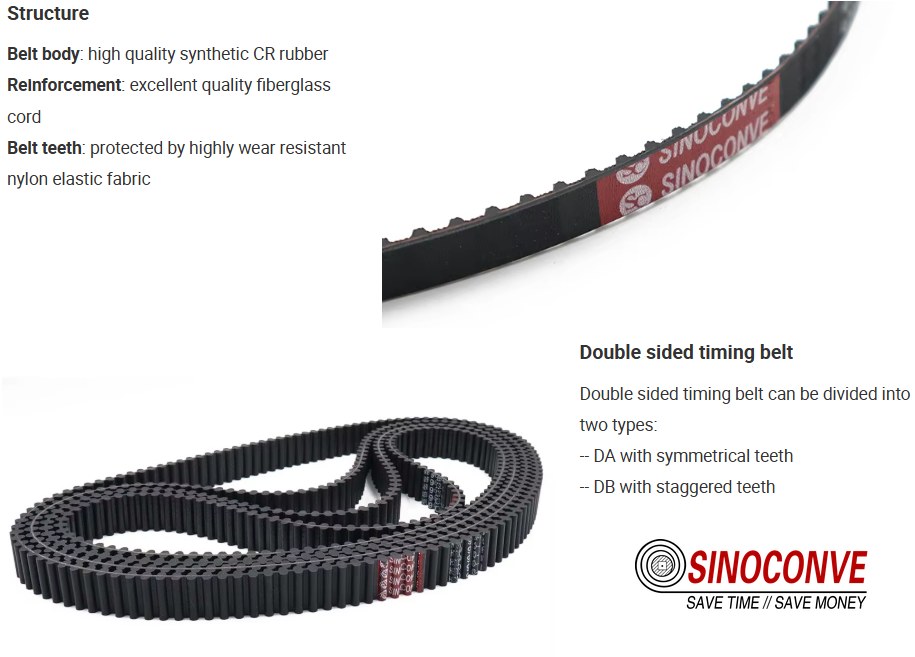
Cord direction sounds like a detail until you assemble a belt the wrong way round. A twisted cord wants to untwist when it is put under tension. If the twist runs one way on the top ply and the other way on the bottom ply, the belt is balanced and the tension tries to rotate the belt about its own long axis only very slightly. If both plies run the same way, the belt develops a small but persistent twist under load, and on a long centre distance that twist turns into a tracking drift that no amount of tensioning will cure.
Direction also interacts with the teeth. On a fine pitch with shallow teeth, the cord sits close to the tooth roots and the direction of lay determines which side of the tooth the cord reinforces first under load reversal. On drives that reverse, this matters; on drives that only turn one way, it barely does. So we ask two questions before we set the lay: does the axis reverse, and is the centre distance longer than roughly forty times the pitch? Two yes answers and we balance the cord. Two no answers and a single direction is fine and cheaper.
| Cord Direction | Relation to Tooth Engagement | Assembly Orientation | Typical Use |
|---|---|---|---|
| S lay, single direction | Reinforces one flank of the tooth first | Marked side outward toward the drive pulley | Single-direction indexing, short centres |
| Z lay, single direction | Mirror of S lay; watch the tracking direction | Follow the mould mark, do not flip | Mirror-image machines, paired lines |
| Balanced (S plus Z plies) | Symmetric reinforcement both flanks | Either face may run outward | Reversing axes, long centres |
What the mould mark tells you
If a belt arrives with a mould mark and you cannot recall which face it points at, do not guess. Run it briefly at low speed with a straight edge against the belt edge and watch for a slow wander. A balanced belt will wander less in one direction than the other; a single-direction belt will favour one side and stay there. Ten minutes of that test saves a week of arguing about pulley alignment.
04Elongation Behaviour Under Load
Every belt stretches when it is put on the machine, and then stretches a little more when it is loaded. Those are two different numbers and designers mix them up constantly. Installation elongation is what the belt does while you are pulling it onto the pulleys with the take-up slack. Working elongation is what it does on top of that once torque is applied. For an aramid cord belt the sum is small, and that is the whole reason people choose aramid. But "small" is not zero, and a drive that assumes zero will run out of take-up travel by month four.
A worked example on a real centre distance
Take a T10 drive, 32 teeth on the driver, centre distance 480 mm, ambient 24 degrees C, normal shock. We set installation elongation at 0.3 percent by feel and deflection, and we expect working elongation under full torque to add about 0.2 percent. On 480 mm that is roughly 1.4 mm of installation take-up plus 1.0 mm of working take-up, so the take-up must be able to absorb a little over 2 mm, plus margin. Give it 4 mm and forget about it. Give it 1 mm and you will be back in six weeks.
| Condition | Elongation (%) | Tension (N/mm) | Take-Up Needed |
|---|---|---|---|
| First fit, cold, unloaded | 0.30 | Seed tension only | About 1.4 mm on 480 mm centres |
| Run-in, 24 hours | 0.35 to 0.40 | Partial load | Re-check and reset once |
| Full torque, steady | 0.50 | Design working tension | Adds about 1.0 mm on 480 mm centres |
| Shock or jam event | Spike, then partial recovery | Up to twice working | Inspect cord, reset tension, log event |
Two practical warnings. First, elongation is quoted at a reference temperature; a belt fitted cold outdoors at 5 degrees C and then run in a 40 degrees C enclosure will lose some of its seed tension as it warms, and that is a tension change, not permanent stretch. Second, if you measure elongation with a tape along the tooth tips rather than the pitch line, the number will be wrong, because the tooth tips do not follow the same path as the cords. Measure on a known tooth count, or measure centre distance change and back-calculate.
Design engineers who are more used to friction drives sometimes expect the belt to slip before it fails, as a V belt does. A synchronous belt does not slip. It ratchets, jumps a tooth, and destroys the timing reference in a single step, which is why the elongation and take-up numbers on this page deserve more respect than they usually get. The same principle underlies the transmission work we do on the V-belt side, but the failure signature is completely different, and confusing the two leads to the wrong fix.
05Tension Behaviour and Take-Up Range
An aramid cord belt likes to run slack compared with what most mechanics expect. The reason is that the cord carries the load, not friction, so the belt only needs enough tension to keep the teeth seated and to stop the slack side from whipping. Over-tension buys you nothing but cord fatigue, bearing load and a shorter life. Under-tension is not much better: the teeth climb the pulley flanks, the pitch line wanders, and positioning accuracy drifts before any visible damage appears.
The deflection method still works and it is still what most of our field people use. Press the belt at the middle of the span with a straight edge and a modest thumb force, and read the deflection. The old figure of one sixty-fourth of the span is a reasonable starting point for aramid drives at moderate speed, and we usually land between 10 mm and 12 mm on a 480 mm span. Below 8 mm you are probably too tight. Above 18 mm you are certainly too loose.
| Method | What You Measure | Reset Frequency | Acceptance Criterion |
|---|---|---|---|
| Deflection gauge | Mid-span deflection under thumb force | First week, then every 500 hours | 10 to 12 mm on a 480 mm span |
| Sonic tension meter | Natural frequency of the free span | Commissioning, then quarterly | Within 10 percent of the design tension |
| Centre distance log | Take-up position, written down | Every inspection | Less than 0.5 mm drift per quarter |
| Idler load cell | Reaction at a tensioner idler | Critical drives only | Trend, not absolute value |
The number nobody writes down
Write the take-up position down at commissioning, on the machine, in paint or on a tag. Six months later that single number tells you whether the drive has settled gently or whether something is stretching that should not be. A cord belt that needs more than about 1 mm of take-up per quarter on a short centre distance is telling you something, and it is usually not the belt.
06Precision Positioning and Repeatability
Precision is not one number, it is three, and buyers who quote a single figure usually quote the wrong one. Repeatability is how closely the axis returns to the same position from the same direction. Hysteresis is how far it lands when it approaches from the opposite direction. Cumulative pitch error is how much the belt's tooth spacing drifts over its whole length. A drive can repeat within 0.05 mm and still show 0.4 mm of hysteresis, and a designer who only asked about repeatability will be baffled when the second approach misses.
Aramid cord helps all three, because low cord stretch means the belt does not keep relaxing and creeping between moves. But cord construction helps only if the tooth spacing is right, and the belt length is right. We have seen a belt repeat beautifully on fresh tension and then drift 0.3 mm within a week, and the cause was a take-up that had been set to the wrong side of its travel. The belt was fine. The mount was out of adjustment.
| Metric | Typical Figure | How It Is Quoted | What Erodes It |
|---|---|---|---|
| Repeatability | Plus or minus 0.1 mm at the axis | Same direction, same load, many cycles | Loose tension, worn teeth, poor pulley runout |
| Hysteresis | Often two to four times the repeatability figure | Approach from both directions and compare | Cord twist, tooth backlash, frame compliance |
| Cumulative pitch error | Fraction of a millimeter over full length | Across a measured number of teeth | Mould wear, cord tension variation during lay |
Where a belt feeds a product rather than a tool, the tolerance chain usually sits elsewhere and the belt's own error is a smaller contributor than most people assume. That is the case on much of the automation we supply, including the PU timing belt for packaging robotics work and the surface work covered in our notes on PU timing belt surface precision. Check the whole chain before you blame the pitch.
07Small Pulley and Back-Bend Limits
Why aramid cord dislikes small pulleys
This is the section where aramid cord earns its reputation for being unforgiving, and it is worth being blunt about why. Aramid has very high modulus, so it resists stretching, and that same stiffness means it does not like being bent tightly. Bend it repeatedly around a pulley below the minimum diameter and the cord takes compression on the inside of the curve that it was never designed to take. Do that a few million times and the cord filaments start to break from the inside out. You will not see it until the belt fails.
Every pitch has a minimum pulley tooth count, below which the cord stress at the root of each tooth becomes unacceptable. Those counts are usually quoted by the belt supplier and, more importantly, they are usually quoted for the standard cord, not for a high-modulus aramid cord. If you are using high-modulus cord, add margin. Our practical rule is that the driver pulley should never be below the published minimum, and if your drive only has thirty teeth to work with, we would rather talk you into a finer pitch than push a coarse pitch onto a small pulley.
| Pulley Teeth (Driver) | Min Diameter Guidance | Back-Bend Guidance | Risk if Exceeded |
|---|---|---|---|
| Under 20 teeth | Avoid on aramid cord; use fine pitch only | No back-bend at all | Cord fatigue at the tooth root within months |
| 20 to 30 teeth | Acceptable for T5 and 8M at moderate load | Only with a large back-bend idler | Accelerated cord aging, heat build-up |
| 30 to 60 teeth | Comfortable for most pitches up to 14M | Allowed with a generous idler radius | Low, provided tension is correct |
| Over 60 teeth | No practical lower limit concern | Normal practice | Pulley cost and inertia become the issue |
Field note from our engineers: A converter ran aramid cord belts on a rotary knife drive and kept destroying them after about five months. The timing was fine, the load was modest, the pitch was right. The problem was a flanged back-side idler used to hold belt tension, and the idler was small enough that the belt was bending backwards around it several times a second. We replaced the idler with a larger one and raised the deflection from 6 mm to 11 mm, and the next belt ran past eleven months on the same duty. Back-bend, not load, is what kills aramid cords.
On the general point of precision drives, cords and pulleys have to be considered as a system rather than two purchased items. That is the angle we take in our precision drive timing belt notes, and it is also why a supplier who also builds a transmission belt manufacturer line of friction drives tends to be more careful about pulley geometry than a pure trading house.
08Tooth Geometry and Pitch Matching
The tooth profile has to match the pulley groove, and "match" means more than "same pitch". Depth, flank angle and root radius all matter, and they are set by the pitch family. Put a trapezoidal belt on a round-profile pulley, or the reverse, and the belt will seat on the wrong surfaces, ride high, and wear the tooth flanks at a rate that looks like a material fault. It is not. It is a geometry fault.
The engagement ratio matters too. That is the number of teeth in mesh on the small pulley. Below six teeth in mesh, load per tooth climbs quickly and torque capacity drops; below four, most engineers will not sign off at full load. On a small pulley you can recover engagement by using an idler to increase wrap, but you have just added a back-bend, so read the previous section again before you do it. Geometry decisions do not live in isolation on a synchronous drive.
| Feature | Typical Range | Effect on Drive | Check |
|---|---|---|---|
| Tooth depth | Roughly 40 to 60 percent of pitch | Deeper tooth carries more torque per tooth | Confirm against pulley groove depth |
| Flank angle | Set by pitch family | Wrong angle means point contact and fast wear | Trapezoidal versus round profile |
| Root radius | Sized to the cord bundle | Too small and the cord is pinched at the root | Inspect a cut section under magnification |
| Teeth in mesh | Six or more preferred | Directly scales torque capacity | Count on the drawing, not on the machine |
09Assembly Without Damaging the Cord
Most aramid cord damage happens in the ten minutes it takes to fit the belt, not in ten thousand hours of running. The cord does not tolerate being levered over a pulley flange, being folded back on itself to get around a frame member, or being gripped in a vice to hold it while you pull. Fit the belt straight, on the pulleys, with the take-up fully slackened. If you cannot get it on without folding it, the frame is wrong, not the belt.
Never use a screwdriver as a lever on the teeth. Never let the belt hang folded over a sharp edge while you fetch a tool. And never re-use a belt that has been kinked, even if the kink looks mild; aramid cord keeps the memory of that kink and will fail there. We would rather ship a slightly longer belt with a proper idler than watch a fitter force a shorter belt into place.
| Step | Do This | Do Not Do This | Check After |
|---|---|---|---|
| 1. Prepare | Slacken take-up fully; clean grooves | Force the belt over a flange | Grooves free of debris and burrs |
| 2. Seat | Engage teeth by hand, rotate the pulley | Lever with a screwdriver | Every tooth seated, no high spots |
| 3. Tension | Bring to seed tension, observe cord direction mark | Over-tension to stop a slight whip | Deflection within the range from Section 05 |
| 4. Run in | Run unloaded ten minutes, then loaded | Go straight to full production load | No wander, no squeal, no hot cord smell |
Assembly discipline matters even more when the drive sits inside a machine that is hard to open, because a mistake means a second shutdown. On lines of that type, vertical formers especially, the belt is often the last item in and the first to be blamed. We wrote a separate note about the fitting routine for timing belt for vertical packaging machines, and the same rules apply wherever access is tight.
10Tensioning Methods for Aramid Belts
Tensioning is a routine, not an event. The first fit gets the belt running, but the belt will settle, the frame will settle, and the number you set on Friday will not be the number on the machine in March. Build a resettling interval into your maintenance plan and it becomes a two-minute job. Skip it and it becomes a breakdown, usually on the shift when the machine is fully committed.
There are three methods in common use, and they are not equally good. The deflection gauge is cheap, fast and adequate for the majority of industrial drives. The sonic meter is more precise and better for long spans and high-speed axes, but it needs the belt's mass per unit length, and if you feed it a catalog figure for the wrong cord you will get a confident and wrong answer. The centre-distance log is the least glamorous and the most useful over a year, because it is a trend rather than a snapshot.
| Method | Skill Needed | Interval | Decision Rule |
|---|---|---|---|
| Deflection gauge | Low | 500 hours, or weekly on critical lines | Reset if outside 10 to 12 mm on a 480 mm span |
| Sonic meter | Medium; needs correct mass figure | Commissioning and quarterly | Reset if more than 10 percent from design |
| Centre-distance log | Very low, needs discipline | Every inspection | Investigate drift over 0.5 mm per quarter |
| Automatic tensioner | Design-stage decision | Inspect travel quarterly | Must not bottom out against its stop |
Temperature belongs in the same log line
One habit we push with every aramid drive we sell: record the ambient temperature at the same time as the tension reading. A cord belt fitted at dawn in a cold plant and checked at noon in a hot one will read differently, and a maintenance planner who does not know that will order belts for a stretch problem that does not exist. Temperature and tension belong in the same log line.
11Thermal and Chemical Limits in Service
The PU body of an aramid cord timing belt sets the temperature ceiling, and the cord sets the lower limit. Standard PU is comfortable to about 80 degrees C in continuous service and can survive short excursions higher than that, but aramid cord loses a share of its strength as temperature climbs and does not get it all back on cooling. Below roughly minus 20 degrees C the PU stiffens and the belt can crack at the tooth root on the first cold start, especially if it has been sitting slack on an outdoor frame.
Chemistry is the quieter risk. Oils, cutting fluids and some cleaning agents attack the PU over months rather than days, and the damage looks like a soft, shiny tooth surface before anything actually breaks. If the drive lives near a misting operation, say so when you order, because there is a difference between a general-purpose PU and one formulated for oily environments. The belt choice question sits alongside the PU versus rubber question discussed in our PU timing belt vs rubber timing belt comparison; here we only note that neither body material changes the cord's temperature sensitivity.
| Exposure | Comfortable Range | Effect on the Belt | Mitigation |
|---|---|---|---|
| Continuous heat | Up to about 80 degrees C for standard PU | Cord strength drifts down; PU ages faster | Heat-resistant grade, ventilation, shorter intervals |
| Cold start | Down to about minus 20 degrees C | Stiff PU, tooth-root cracking on first move | Warm-up rotation, avoid slack cold starts |
| Oil mist | Depends on the formulation | Swelling, softened tooth surface, gradual loss of pitch | Oil-tolerant compound; shield the drive |
| Abrasive dust | Not a cord issue, a tooth issue | Tooth flank erosion, then backlash | Enclosure, or accept shorter life |
12Failure Modes Specific to Cord Belts
Cord belts fail in ways that friction belts do not, and reading the failure correctly saves money, because the wrong remedy usually makes things worse. A tooth stripped over its full width is a load or engagement story. A tooth cracked at the root is a tension story. A belt that has grown long enough to run out of take-up but shows no visible damage is a cord creep story, and that one deserves a call to the supplier before you simply shorten the centre distance.
Read the failure before you replace the belt
We keep a small chart of symptoms on the wall of the workshop, and we update it whenever a returned belt surprises us. It is not exhaustive, and no chart is, because a real failure usually has two causes layered on top of each other. Still, it beats guessing.
| Symptom | Mechanism | Early Sign | Corrective Action |
|---|---|---|---|
| Tooth stripped full width | Ratchet from shock load or too few teeth in mesh | Slight timing drift on a hard start | Raise engagement, soften start, check torque peak |
| Tooth-root cracking | Over-tension, small pulley, cold start | Fine surface crazing near the root | Reset deflection, enlarge pulley or idler |
| Permanent length growth | Cord creep or cord damage during fitting | Take-up position creeping outward | Inspect for kinks, then discuss with supplier |
| Edge cord fray | Misalignment, flange rubbing, tracking against a guide | Shiny belt edge, fine dust at the pulley | Realign the frame, remove the rub point |
| Soft, shiny teeth | Chemical attack on the PU body | Tooth looks polished rather than worn | Change compound, shield the drive, review wash-down |
It helps to remember that a timing belt is a small part of a bigger machine, and its failure often reflects the machine. Our broader notes on rubber timing belt application make the same point for the rubber variant, where the same modes show up with a different timeline.
13Inspecting for Cord Damage and Pitch Wear
Internal cord damage is the hardest thing to see, because the cord is buried inside the belt and everything that fails first is invisible until it reaches the surface. There is no single inspection that proves a cord is sound, so the practical approach is to look for the earliest external evidence and to measure rather than look. Most of what you need is a straight edge, a caliper, a good light and a logbook.
The two-minute inspection is worth more than the annual teardown. Check pitch across twenty teeth, look at the tooth flanks with a light at a low angle, feel the belt edges for fray, and read the take-up position. Any one of those four drifting is a signal. All four stable and you can leave the belt alone.
| Check Item | Tool | Acceptance Rule | Interval |
|---|---|---|---|
| Pitch over 20 teeth | Calipers and straight edge | Within a small fraction of nominal | Quarterly |
| Tooth flank wear | Light at a low angle | No visible step, no shine | Monthly |
| Belt edge condition | Hand and eye | No protruding cord, no fray | Monthly |
| Pulley groove wear | Groove gauge or pin | Within the maker's limit | Annually |
| Take-up position | Straight edge and marker | Less than 0.5 mm drift per quarter | Every visit |
Surfaces are where wear announces itself first, and treating the surface as an inspection window rather than decoration is a habit worth building. The ideas behind rubber timing belt surface innovations were developed for exactly that reason, and they transfer to the PU side as a mindset even where the material differs.
14When Steel Cord Still Wins
We deal with the aramid versus steel cord decision elsewhere, and we will not rebuild that comparison here: if you want the side-by-side on cost, stiffness and failure signature, read aramid fiber vs steel cord PU timing belt and come back with a pitch. This page exists for what happens after that choice is made.
| Situation | Practical Reading |
|---|---|
| You still need a carcass decision | Use the comparison article linked above; the pitch work on this page applies either way. |
15Design Inputs Checklist
Before a quotation is worth anything, the supplier needs enough of your drive to catch the traps. Most RFQs we receive are missing at least three of the items below, and the missing ones are almost always the ones that decide whether the belt lasts. Fill the checklist in once and reuse it across every drive on the line.
What to ask any belt source
What separates a good belt source from a catalog is how the source behaves when your numbers are unusual. Anyone can sell a T10 belt. Ask a candidate how they control cord tension during lay, and how they prove it after curing. Ask whether the same press also runs an industrial conveyor belt for a crusher circuit, because a plant that has to satisfy that duty tends to have better process control than one that only makes light belting. We are happy to be asked. As a conveyor belt supplier to aggregate and bulk operations, and equally as a conveyor belt distributor partner for branded lines, we see both ends of the tolerance argument.
If your purchase sits inside a larger project, the practical starting points are the wholesale conveyor belts listing for volume enquiries and the general product catalog for a single line item. If you want to know how a timing belt manufacturer for automation normally runs an OEM program, that article answers it; and if your drive is a friction drive rather than a synchronous one, the same engineering team works as a V-belt manufacturer and will route you there.
| Input | Why It Changes the Quote | Missing It Causes |
|---|---|---|
| Pitch and tooth profile | Sets the mould and the cord spacing | A belt that will not seat on the pulley |
| Driver and driven pulley teeth | Determines minimum diameter and engagement | Cord fatigue from day one |
| Centre distance and take-up travel | Sets belt length and elongation budget | Running out of adjustment in months |
| Torque, speed and duty cycle | Chooses cord construction and count | Tooth ratchet on the first hard start |
| Back-bend geometry | Decides whether aramid is viable at all | Internal cord failure with no visible cause |
| Temperature and chemistry | Selects PU grade and cord protection | Premature aging, shiny softened teeth |
| Positioning tolerance | Sets the acceptable pitch error | A belt that repeats but will not hold |
16Specification Sheet: Numbers to Write in the RFQ
Here is the field list we would like to receive. It is short on purpose. If you send these eleven fields, we can quote without a round of questions, and the belt that arrives will behave like the belt you designed rather than like the belt we guessed at.
One last thing on the sourcing side: it is worth knowing who actually owns the press. A plant that calls itself a conveyor belt factory should be able to show you the mould hall and the tension bench, and should be able to explain why a aramid timing belt is cured at one pressure and a general-purpose belt at another. If the answer is a shrug, the cord tension is not being controlled either.
| Field | Unit | Mandatory | Reason | Example |
|---|---|---|---|---|
| Pitch code | T or AT or M series | Yes | Selects the mould | T10 |
| Belt length | mm or tooth count | Yes | Sets the cord length under lay | 1,300 mm |
| Belt width | mm | Yes | Sets cord count and web width | 50 mm |
| Driver pulley teeth | count | Yes | Minimum diameter check | 32 |
| Design torque | N.m, with peak | Yes | Cord rating and count | 9 N.m steady, 20 N.m peak |
| Speed | rpm or m/s | Yes | Heat build-up and fatigue check | 1,200 rpm |
| Back-bend radius | mm, or none | Yes | Viability of aramid cord | None |
| Ambient temperature | degrees C, max and min | Yes | PU grade selection | 5 to 45 |
| Chemical exposure | list | Recommended | Compound review | Light oil mist |
| Positioning tolerance | mm at the axis | Recommended | Pitch error budget | Plus or minus 0.1 mm |
| Endless or open | type | Yes | Changes the curing and the joint | Endless |
Lead time and minimum order for aramid cord belts follow industry norms and depend on whether the mould exists; typical ranges run from stock for common pitches to several weeks for a new mould, and the exact figure is always confirmed against the actual duty and drawing. Nothing on this page replaces that confirmation.

17Frequently Asked Questions
How do I choose the pitch for an aramid cord drive?
Start from the smallest pulley that already exists on the machine, because that is what limits how fine you can go, then check the positioning tolerance the axis actually needs. Only after those two do you look at belt width. A pitch picked from a load table alone usually overshoots and forces an unnecessary pulley change.
What elongation should I expect from an aramid cord belt?
Plan for roughly 0.3 percent at installation and about 0.2 percent more under full working load, so around half a percent total. On a 480 mm centre distance that is a little over 2 mm of take-up travel. Give the take-up 4 mm of range and the number stops being a worry.
Why does cord direction matter on assembly?
Because a twisted cord tries to untwist under tension. If the plies are balanced, the belt stays flat; if they are not, a small twist appears under load and turns into a tracking drift that grows with centre distance. Fit the belt with the mould mark on the specified face and do not flip it.
What is the smallest pulley an aramid belt can run on?
That depends on the pitch and the cord construction, and the answer is always quoted in pulley teeth rather than millimeters. Under 20 teeth on the driver is a warning sign with aramid cord; 20 to 30 is workable at moderate load with a fine pitch; above 30 teeth you have room to work. Never use the minimum for a steel cord belt as the minimum for aramid.
Is back-bending ever allowed?
Sometimes, but only with a generous idler radius and only when you have no alternative. Aramid cord hates being bent against its natural direction, and a small back-bend idler running at speed will destroy the cord long before the teeth show any wear. If your design has a back-bend idler, tell us the diameter at quotation stage.
How often does an aramid belt need re-tensioning?
Twice in the first month, then almost never. If nothing else changed after that, a drive asking for tension every few weeks has a mounting or alignment problem.
What temperature limit should I design to?
Design to about 80 degrees C continuous for standard PU, and keep cold starts above roughly minus 20 degrees C. The cord is the part that suffers when you push past the top of that range, and the PU is the part that suffers at the bottom. If your machine runs near either edge, say so when you order.
How do I inspect for internal cord damage?
You cannot see it directly, so you look for the signs it leaves behind: permanent length growth, a take-up position that keeps moving, or edge fray where the cords run. Measure pitch across twenty teeth and compare with the previous reading. If the length is stable and the pitch has not moved, the cord is probably sound.
What causes pitch wear on a precision drive?
Three things, usually together: abrasive dust in the grooves, a pulley that has worn out of spec, and a belt run too tight. Change one at a time and measure after each, because replacing the belt while the worn pulley stays in place just resets the clock on the same failure.
When is aramid the wrong choice?
When the pulley is genuinely too small to change and the load is real. Aramid will not tolerate it, and neither will any amount of clever tensioning. In that case the honest answer is a different pitch, a redesigned drive, or a compliant cord that sacrifices some precision for survivability.
What tolerance does repeat positioning need?
Ask the axis, not the catalog. Most packaging and pick-and-place axes repeat comfortably within plus or minus 0.1 mm on a well-tensioned aramid belt; machine-tool axes that need tighter will also need a stiffer frame, because the belt is rarely the largest error in the chain.
Which numbers belong in the RFQ for an aramid belt?
Pitch, belt length, belt width, driver pulley teeth, torque with peak, speed, back-bend radius, temperature range, chemical exposure, positioning tolerance and whether the belt is endless or open. Eleven fields. Send those and the quotation stops being a guess.
18Related Products You May Need
- Timing belts in PU and rubber for synchronous drives across the pitch range.
- V-belts and banded drives where a friction drive is the better answer.
- Rubber conveyor belts for the material-handling side of the same plant.
- Full product catalog for a single consolidated enquiry.
19Related Blog Posts
- Aramid fiber vs steel cord PU timing belt for the carcass decision this page assumes is already made.
- Timing belt types and pitches for the wider family view.
- PU timing belt vs rubber timing belt when the body material is still open.
- Aramid fiber PU timing belt strength and efficiency for the cord material itself.