

The drive holds together on four numbers. Set the section profile, the two pitch diameters, the wrap angle on the small pulley and the static tension correctly, and a belt will run quietly for years; set any one of them wrong and it slips, rolls over in the groove, or snaps long before its rated life is up. Almost every failure we are called out to inspect traces back to one of those four. We cover how a drive behaves on a real shaft rather than how a belt is built, so the construction side is assumed.
We mould transmission belts and heavy conveyor belting in Ningbo, and we size grooved drives every week for mines, quarries, cement plants and general industrial floors, which is why the questions we field never really change. Which section suits the duty? How many belts does the load actually need, and how tight should they sit on the pulleys? When is a V-belt plainly the wrong tool? Those three come up almost every time. Send us a motor nameplate and we will run the worked example below against it, the way our engineers do when a customer asks for a matched set.

01How an industrial V-belt drive turns torque into grip
Torque arrives at the small pulley at a fixed speed, and the belt has to carry it across the span without letting the two shafts drift out of step. Wedge action does the work. Flank pressure against a 40 degree groove multiplies the grip on offer, so a belt that would skate on a flat rim at the same tension digs in and pulls hard, and that multiplying effect grows as load comes on. Nearly every rule below grows out of that single piece of geometry.
Three levers decide how much grip a V-belt really has
Start with the wedge. A classical A, B, C or D belt is moulded at a 40 degree included angle, and the groove is cut to match so both flanks lie flat against the walls and carry the load. Take the A section. It measures about 13 mm across the top and 8 mm high, and the groove cut for it follows the same angle. Let the two angles disagree and contact collapses onto a single edge, after which the belt either rides high and slips or wedges too deep and cooks. We see that most often when a belt from one maker is dropped into a groove cut for a different family, and the drive then eats belts while never running anywhere near its rated power. Because we cut both the belt and the groove reference, we judge the pair together, which is the habit behind every transmission belt manufacturer we respect.
Wrap angle is the second lever, and it costs more capacity than most buyers expect. Call it pure geometry. Torque capacity falls roughly with the arc of contact, so a belt running at 120 degrees of wrap will not carry what the same belt carries at 180. Large speed ratios, short centre distances and outside idlers all steal wrap. On a 22 kW fan drive in a cement plant, we measured 128 degrees on the small pulley and had to add a fourth belt to hold the load; widening the centres by 150 mm put the wrap back near 160 degrees and dropped the count to three. Measure the wrap before blaming the belt for slipping, because it is the first number that tells you whether the grip was ever there.
Tension converts the wedge into usable friction. Without enough static tension the belt sits shallow, touches the groove along a narrow band and slips the moment load arrives, which is why the most common field complaint, a squeal under starting torque, is nearly always a tension problem rather than a belt problem. Set it with the deflection rule. Record what you set, too.
| Drive variable and what it fixes in the drive | What goes wrong when it drifts out of range, and how we check it on site |
|---|---|
| Section profile and top width, which caps the power one belt can carry at a given speed and pulley size | An undersized section runs hot and stretches early, while an oversized one adds bearing load, so we gauge width and height against the profile drawing |
| Pulley pitch diameter, measured on the driver shaft and the driven shaft | A pulley below the section minimum cracks the belt from the inside out, so we compare the measured pitch diameter with the minimum on the drawing |
| Arc of contact, in degrees, over which the belt wraps the small pulley | Large ratios and outside idlers remove capacity long before the belts look worn, so we calculate the wrap from the centre distance and the two diameters |
| Static tension set at installation and recorded by the fitter in the log | Loose belts slip and glaze, while over-tight belts load the shaft and bearings hard, so we apply the deflection rule with a spring gauge |
| Parallel offset and angular alignment between the two facing pulley faces | Offset and twist drive edge wear, rollover and a rhythmic squeak, so we lay a straightedge across both pulley faces and look for daylight |
| Matched length spread across a set of two or three belts on one drive | The shortest belt does the work and fails first while the rest still look new, so we measure every belt on one tensioned rig |
02The section profile family: A, B, C, D and the SPZ to SPC metric range
Choose the section before anything else, because it caps the power one belt can carry and sets the smallest pulley the drive can use. Two families cover almost every drive. The classical inch range runs A, B, C and D, while the metric SP range runs SPZ, SPA, SPB and SPC. Nominal figures are consistent across makers, but the workable minimum pulley diameter moves with speed and load, so treat the table below as a starting point and confirm it against a belt maker's own catalogue. An undersized section can fail inside a month.
How load capacity scales with the cross-section, and the smallest pulley that keeps a belt alive
A taller, wider section carries more power because it holds a heavier cord and seats on a larger flank area. Numbers make the point. One A-section belt tops out near 4 kW at normal speed, so a 30 kW duty needs a B or a C section, or four A belts running as a matched set, while the same duty fits inside a single D groove. We work from a capacity table for each profile, as any V-belt manufacturer does, and your job at the RFQ stage is to state the real continuous power and the peak starting torque.
Every section has a smallest sensible pulley, and dropping below it does not fail the drive at once, which is exactly what makes the mistake so common. The belt simply bends harder on every pass, the cord fatigues faster, and months later the belt splits at the base in a way that always gets blamed on the belt rather than on the design itself. Below that floor, life falls away fast. Go up a section or up a pulley size when the frame is tight.
Speed, heat and section size move together. Belt speed follows from pulley diameter and shaft rpm, and it drives both heat and belt life. Below about 5 m/s the wedge has too little time to build grip, while above roughly 30 m/s centrifugal force starts to lift the belt clear of the groove and strips capacity away. Most industrial drives sit between 10 and 25 m/s. Inside that band a larger pulley turning slowly outlasts a small pulley turning fast almost every time, and our 15 kW bucket-elevator example lands at 17.0 m/s for exactly that reason, well inside the comfortable window.
| Profile with its nominal top width and height, and the smallest pulley we allow | Power one belt carries at normal speed, and the duty where the profile earns its place |
|---|---|
| The classical A section measures about 13 mm across the top by 8 mm deep, with a smallest pulley near 75 to 90 mm | About 1.5 to 4 kW per belt, which suits small fans, pumps and light machine tools on compact shafts |
| The classical B section measures about 17 mm across the top by 11 mm deep, with a smallest pulley near 125 to 140 mm | About 3 to 8 kW per belt, a good fit for compressors and conveyors run as a matched set of two or three |
| The classical C section measures about 22 mm across the top by 14 mm deep, with a smallest pulley near 180 to 200 mm | About 7 to 20 kW per belt, for mills, large fans and quarry equipment on near continuous duty |
| The classical D section measures about 32 mm across the top by 19 mm deep, with a smallest pulley near 300 to 355 mm | About 15 to 40 kW per belt, for heavy drives where one belt replaces a whole set of smaller ones |
| SPZ is the narrowest metric section at about 10 mm across the top by 8 mm deep, with a smallest pulley near 63 to 75 mm | About 0.5 to 2 kW per belt, for light metric machinery and precision drives built to a European standard |
| SPA measures about 13 mm across the top by 10 mm deep, with a smallest pulley near 90 to 100 mm | About 1.5 to 5 kW per belt, a natural retrofit where an A-section groove is already cut |
| SPB measures about 17 mm across the top by 13 mm deep, with a smallest pulley near 140 to 160 mm | About 4 to 12 kW per belt, for general metric industry that once used a B section in inches |
| SPC is the heaviest metric section at about 22 mm across the top by 18 mm deep, with a smallest pulley near 224 to 250 mm | About 12 to 30 kW per belt, for large metric drives that would otherwise need a C or a D belt |
03Wedge angle and effective diameter: where the speed ratio really comes from
The ratio you get is not outside diameter over outside diameter. The gap surprises people. A V-belt runs at its pitch line, a position inside the section near the cord, and only the diameter at that line counts when you work out driven speed, which on a 200 mm B-section pulley lands near 195 mm, a shift large enough to move the ratio where the driven machine tolerates only a narrow speed window.
Why the belt rides high in the groove, and what groove wear does to the ratio
The belt does not sit flush. It rides proud by a few millimetres, because only the flanks touch and the base stays clear so the wedge can work, and the higher it rides the larger the effective diameter and the faster the driven shaft turns. A fresh belt sits at its designed height. Let it stretch and thin, though, and it drops deeper in the groove, so the output speed sags just enough to throw a process off.
Grooves are a wear surface, and as the flanks wear the groove widens and the belt drops deeper. The change creeps along at a few tenths of a millimetre a month, yet it only ever goes one way. We have pulled pulleys whose grooves had opened by 3 mm, and the operator's only complaint was that the machine had quietly lost speed across a season while nothing on the drive looked worn enough to explain it. Gauge groove width at every major service. A worn pulley will wreck a fresh matched set in a fraction of the time it should take.
04Arc of contact, elastic creep and the difference from true slip
Wrap and slip get lumped together far too often, and that sends crews chasing the wrong fault. Arc of contact is pure geometry, the angle over which the belt touches the small pulley, and it sets the ceiling on the torque that pulley can pass. Elastic creep works differently. As a belt takes up tension on the tight side and gives it back on the slack side, the cord stretches and recovers, so the belt surface creeps microscopically against the pulley even when the drive is running perfectly.
Telling elastic creep apart from real slip
Real slip is what happens when the flanks break away and the belt skates in the groove. It behaves nothing like creep. Creep stays quiet and steady, while slip announces itself with heat, a squeal under load and a belt that turns glossy in patches. The quick test is to read where the shine falls. Creep leaves the belt uniform. Slip polishes the groove base and the flank edges that lose contact first. As a conveyor belt manufacturer we spend our days on drives where the belt has to grip for years, and that read of shine patterns applies whether the belt climbs an incline or turns a fan.
05Tension: how much to set, and how often to recheck it
Tension is the one variable a maintenance team can control without changing hardware, which makes it the first thing to set right and the thing most often left to guesswork. The correct static tension depends on the section, the number of belts, the belt speed and the torque the drive carries, so two drives that look identical on the outside can call for very different settings. For a C-section belt on a 700 mm span a maker might call for a 45 N push at the midpoint and a 10 mm sag. The rule on the floor is simple. Press the belt at the midpoint of the longest span with a known force and check the deflection.
The deflection rule and a tension log that pays for itself
We ask every site to keep a simple tension log that records the date, the ambient temperature, the deflection reading and the belt set number, and that single page catches more problems than any one inspection. The log earns its keep because tension drifts. A new belt stretches through its first few dozen hours, and ambient temperature moves the reading between a cold morning and a hot afternoon. On a 15 kW bucket elevator we sized at a 1.2 service factor, the first weekly reading came back ten percent under setting, and the log caught it long before the belt could glaze. As a conveyor belt supplier we see the same seasonal swings on long conveyor runs, and the automatic take-up that fixes them there has no equivalent on a fixed-centre V-belt drive, so the discipline has to come from the schedule.
06Matched sets and the equal-length rule for multiple belts
When a drive carries more than one belt, the belts only share the load evenly when their lengths match closely, and that single requirement turns out to be far stricter than almost any buyer expects before the first set starts failing. Put three belts of slightly different length on the same pulleys and the shortest sits tightest, takes the largest share of the torque, runs hottest and stretches first. Its extra stretch then hands load to the next shortest, so the set fails one belt at a time in a pattern that reads as random but comes straight back to the length spread. A matched set exists to close that gap.
What a matched set guarantees, and what it does not
A matched set is a group of belts selected so their lengths fall inside a tight band, often quoted as a length code or a maximum spread of a millimetre or two. What it does not guarantee is that the belts came from one batch or one cord lot, so the spread is measured, not assumed. When one belt fails, replace the whole set rather than drop a new belt beside worn ones, because the new belt simply becomes the shortest and takes all the load. On the conveying side, where a rubber conveyor belt carries the load as a single unit, this problem does not arise, which is one reason the two families are sized on different rules.
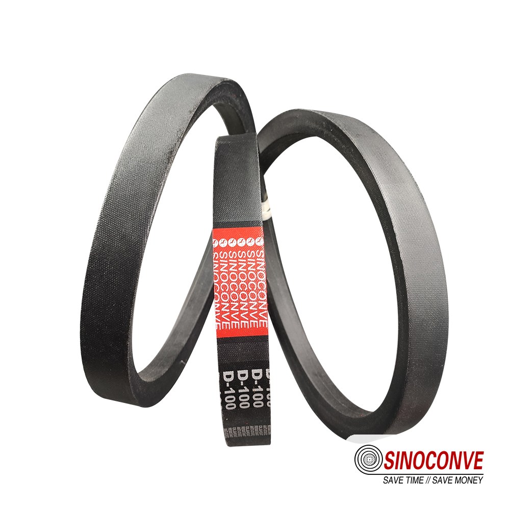
07Alignment and offset: the quiet cause of most premature failures
Alignment failures are the ones that surprise people, because a misaligned drive often runs for weeks before it complains. Two shafts can be parallel but offset sideways, they can meet at a small angle, or both at once, and each fault loads the belt differently. The belt is asked to run in a straight line through the groove while the pulleys try to steer it somewhere else, so it fights the mismatch on every rotation. The cost shows up as heat at a groove edge, a rhythmic squeak that rises with speed, and eventually a belt worn along one edge only.
Parallel offset, angular misalignment and the twist that hides between them
Parallel offset means the two pulley faces are not lined up across the machine, so the belt enters and leaves at an angle. Angular misalignment means the shafts themselves are not parallel, so the belt is twisted slightly as it travels. Both shorten belt life, and angular misalignment is the more destructive of the two because it forces the belt to bend sideways. The field check needs no laser, only a straightedge laid across the face of both pulleys, and you look for daylight at either end before repeating the check across the other face. A belt tracking to one side is the same message arriving from the machine itself, and the logic in our EP conveyor belt tracking guide crosses over to V-belt drives too.
08A worked example: sizing a drive from power, torque and speed
Numbers make the process concrete, so here is a drive we would size from a motor nameplate alone. The duty is a bucket elevator in a quarry, driven by a 15 kW four-pole motor at 1,450 rpm, running about ten hours a day with moderate starting shock. The driven shaft turns at roughly 580 rpm, so the ratio is close to 2.5 to 1. Every step below is arithmetic a buyer can repeat, not a catalogue look-up.
Step one turns motor nameplate power into a design power. Motor nameplate power is what the motor delivers at its shaft, and the drive has to be sized for more than that, because every real machine starts under load and loads vary through the day. The multiplier is a service factor chosen from the duty, and for a bucket elevator on ten hour duty with moderate shock we would use about 1.2. Design power is therefore 15 kW times 1.2, which gives 18 kW. If the same drive started a fully loaded conveyor or a crusher, the factor and the design power would both climb, which is why we ask for the driven machine and the start conditions rather than the motor rating alone.
Step two picks the profile and the two pulley diameters. With 18 kW to place against a speed near 1,450 rpm, a C-section belt fits, since one C belt carries roughly 6 to 9 kW at normal belt speed. The small pulley must stay above the minimum for the section, so we take a pitch diameter of 224 mm, comfortably above the 180 to 200 mm floor for a C profile. The large pulley follows from the ratio, because 224 mm times 2.5 is 560 mm. Belt speed is pi times 0.224 m times 1,450 rpm divided by 60, which comes to about 17.0 m/s, sitting neatly inside the comfortable 10 to 25 m/s band.
Step three settles the belts, the centre distance and the wrap. Divide the design power by the corrected rating of a single belt and round up. At 224 mm and 17 m/s a C belt is good for roughly 6.2 kW once the speed-ratio correction is applied, so 18 kW needs three belts. Set the centre distance at 700 mm as a start, then check the geometry.The wrap on the small pulley is 180 degrees minus twice the angle whose sine is half the diameter difference over the centre distance, which here is about 152 degrees, well clear of the point where grip falls away.Belt length is close to 2,671 mm, so a standard 2,700 mm belt closes the loop, and because that belt is slightly longer than the geometry demands the drive needs at least 25 mm of adjustment to tension it.
| Sizing step and the figure we used on this drive | Why that figure suits a 15 kW bucket elevator |
|---|---|
| Design power, taken as motor power times a service factor of 1.2 | Ten-hour duty with moderate starting shock justifies a factor as modest as 1.2 |
| Small pulley pitch diameter, chosen as the smallest sheave the section allows | The 224 mm driver sheave clears the 180 to 200 mm minimum for a C belt |
| Large pulley pitch diameter, found by multiplying the small diameter by the ratio | 224 mm times 2.5 gives 560 mm, which delivers the 580 rpm the driven shaft needs |
| Belt speed, from the pitch circumference at the driver multiplied by shaft rpm | About 17.0 m/s sits inside the 10 to 25 m/s band where a V-belt grips and cools well |
| Number of belts, from design power divided by the corrected rating of one belt | 18 kW divided by 6.2 kW rounds up to three belts, carrying the load with margin |
| Arc of contact, read as the wrap on the small pulley in degrees | About 152 degrees at 700 mm centres keeps enough grip for three belts to pull |
One more number belongs in the loop, and buyers often leave it out. The centre distance you set on day one is not the one you run for the life of the drive, because every belt stretches as it beds in and the tensioner takes up the slack. Build the base with an adjustable slot or a swing base able to move at least 25 mm, and mark the starting position so the next shift can see how far the belts have moved. If your plant standardises across many drives, our wholesale conveyor belts catalogue shows the same profile logic we apply across transmission and conveying products, and where a drive needs a fixed ratio rather than a flexible one a synchronous timing belt is the better answer.
09Application limits: when a V-belt drive is the wrong answer
A V-belt is a forgiving transmission, and that forgiveness is exactly why people keep reaching for it in conditions it was never meant to handle. Each of its tolerances has a floor, and past the floor the drive turns into a maintenance cost that never quite goes away. Knowing where the floor sits saves a buyer from fitting a drive that will be replaced four times a year.
Heat, oil mist and abrasive dust in the same enclosure
Temperature shortens V-belt life fastest, and the danger is that it is usually invisible from outside the guard. Standard rubber compounds are comfortable up to about 60 °C in continuous service, and a drive in a hot motor room can exceed that without anyone noticing, because the belt still looks sound right up to the point where it hardens and cracks at the base. Oil mist is the second enemy, since a swollen belt loses grip and rides high, while abrasive dust quietly grinds the flanks and the grooves. Where heat and oil arrive together, insist on a heat and oil resistant compound, and where the belt is an industrial conveyor belt doing the same job on another machine, the same compound question applies.
Frequent starts, reversing duty and the demand for a locked ratio
Every start, stop and reversal puts a shock through the belt, and a drive that does it hundreds of times a shift works far harder than the steady load figure suggests. A V-belt can slip a little under shock, but that same slip wears the flanks and heats the belt, so a high-cycle duty shortens life in a way that catch-up tensioning cannot fix. Reversing drives add a second problem, because any slight misalignment then wears both edges of the belt. When a process needs an exact ratio that cannot drift, such as a metering screw, the flexibility that makes a V-belt forgiving becomes a fault, and a synchronous belt is the right choice. Our page for a conveyor belt distributor range shows how distributors weigh that same substitution question.
| Limit you are up against, and what it does to a V-belt drive | The sign that tells you it has happened, and the mitigation we would fit |
|---|---|
| Continuous running temperature above 60 °C, which hardens the compound and cracks it at the base | Belts fail by cracking rather than wearing thin, so specify a heat resistant compound and shield the drive from radiated heat |
| Sustained oil mist or splash, which swells the rubber so the belt rides high and grip falls away | A soft, swollen belt and a drive that keeps needing tension, so move to an oil resistant compound and fix the leak |
| Abrasive dust on the flanks, which grinds belt and groove walls and throws tolerance away early | Grooves widen and belts sit deeper than they should, so guard the drive and schedule groove checks |
| Hundreds of starts and stops a shift, where repeated shock and slip wear the flanks and cook the belt | Glazed, polished flanks and a drive that squeals on every start, so add a soft start or a tougher transmission |
| A ratio that must never drift, where normal creep and stretch move the output speed off the set point | Product quality drifts even though the drive looks healthy, so fit a synchronous timing belt that holds the ratio |
| A pulley smaller than the section minimum, where the belt bends too hard and the cord fatigues | Belts crack from the core outward and shed cord early, so grow the pulley or step up a section |
| Backside idlers that reverse the bend, which stresses the backing and shortens life on the smallest idler | Cracks appear on the top face rather than the flanks, so enlarge the idler or redesign the wrap |
10Failure modes in the field and how to prevent them
Five ways account for almost every V-belt drive failure we are asked about, and each leaves a signature that points back to its cause. Reading the signature correctly stops a maintenance team from replacing a symptom instead of a fault.
Slip, glazing and the belt that rolls over
Slip is the most common complaint and the most over-diagnosed, since it can come from low tension, oil on the flanks, a worn groove or a load larger than the drive was ever sized to carry. The tell is heat and shine. Once a belt has slipped long enough, the flanks glaze to a hard, glossy surface that grips even less, so a drive that began as a tension problem becomes a repeat-buy problem. Rollover behaves in a different way, because the belt twists and runs on its side in the groove, usually because tension is far too low, because the pulleys are badly out of alignment, or because a worn groove lets the belt seat too deep and climb. Rollover is nearly always a setup fault, and correcting alignment and tension clears it.
Breakage, elongation and wear on the pulley grooves
A belt that snaps cleanly has almost always met a shock it could not absorb, or has run on a pulley below the minimum diameter until the cord gave out. Groove wear is the quiet one, because it damages the pulleys rather than the belt, and a new set fitted to worn grooves fails faster than the set it replaced. Last season a quarry returned three belts from a single drive, every one of them found lying on its side, and the whole fault traced back to one groove worn deep enough for the belt to climb. Because we cut grooves as well as belts, and because the same discipline of measuring a wear surface runs through our conveyor belt factory, we would rather a site gauge its pulleys once a year than replace belts four times a year.
| Failure mode and the root cause we usually find for it | Early warning sign, and the prevention that actually holds |
|---|---|
| Slipping under load, from low tension, oil on the flanks, worn grooves or a drive sized below the real load | A squeal on starting and a growing shine on the flanks, so restore tension, degrease the drive and recheck the load figure |
| Glazed flanks, from long term slip that heat-polishes the rubber until it loses grip | Hard, glossy flanks that feel slick and no longer smell of rubber, so replace the belt and remove the cause |
| A belt that rolls over in the groove, from very low tension, bad alignment or a groove worn too deep | The belt found on its side with one chewed edge, so reset alignment and tension and gauge the grooves for depth |
| Sudden breakage, from shock load, a jammed driven machine or a pulley below the section minimum | Belts that part cleanly with little wear elsewhere, so remove the jam, soften the start and check the pulley diameters |
| Progressive elongation, from over-tensioning, sustained heat or oil that slowly attacks the compound | A tensioner that needs winding in every few weeks, so correct the tension, cool the drive and specify an oil resistant belt |
| Pulley groove wear, from abrasive dust, a belt run with too little tension and long service hours | Belts that sit visibly low in the groove and a drive that loses speed, so gauge groove width annually and replace pulleys early |
11Procurement and acceptance fields for an industrial V-belt order
An order that names only a section and a length leaves the maker free to supply whatever satisfies the drawing literally, and the gaps almost always open on the belt that matters most to you. The way to close them is to specify the few fields that decide performance and to name the test that proves each one. A clean RFQ does not need to be long, only specific.
Dimensions, tolerances and the matched-set fields
The dimensional block starts with the cross-section and its top width, height and included angle, then adds the pitch length and the tolerance class. Section dimensions are measured with a gauge at a defined point, because a belt a fraction wide seats differently from one that is nominal. Length is where matching becomes contractual, so state the measuring tension, state the tolerance class, and for a multi-belt drive state the maximum spread allowed across the set. A supplier who cannot tell you the tension at which the length was measured is giving you a number that will not compare with anyone else's.
Compound, tensile and the oil and heat acceptance tests
Two measurements open the order, and both are easy to leave vague. Write the section as a profile letter, a top width, a height and an included angle, and hold all four inside the normal production band, since a belt half a millimetre wide seats at the wrong depth and then fights the groove for a decade. An A section, for instance, runs about 13 mm across the top on a 40 degree flank.
Length is the harder figure to pin down. Name the tolerance class, state the tension at which the length was measured, and cap the spread across a set, because on a three-belt drive the tightest belt carries everything until the others stretch to meet it. We measured nearly four millimetres of spread across the three belts of one drive we sized last spring.
Elongation follows, read under a stated reference load and capped low, because a belt that stretches far at that load will be re-tensioned again and again. Last season a quarry we supply sent back three belts from one drive, each one stretched to a different length, and the batch reference stamped on each back showed that two shipments had been mixed on the shelf.
Marking closes the loop. Insist on a legible brand, profile, length code and a batch or date reference, so that a failure traced back eighteen months later ties to a cord lot instead of a promise. Keep the tensile, oil and abrasion results with that record.
12Choosing between a V-belt, a timing belt and a banded set
The last decision is whether a V-belt is the right member of the family. A single industrial V-belt is cheap, forgiving and easy to tension, so on a fan or a pump it is hard to beat. A banded set joins several belts with a common top tie, which keeps them in step and resists the rollover that troubles loose belts on the heavy, shock-loaded drives you find on crushers and large fans. Timing belts work on teeth rather than friction, hold the ratio exactly, and belong wherever the output speed has to be precise. Three different families, three different duties.
When a timing belt or a banded set takes over from a plain V-belt
A synchronous timing belt takes over when the process cannot tolerate the drift that creep and stretch impose, or when the shafts have to stay in step so that a metering screw or a synchronised roller lets nothing slip out of phase. Choose a banded set when you run several belts on one drive and keep losing individual belts to rollover or uneven load. Two substitutions matter, and a third does not. Stay with a plain V-belt when the load is steady, the ratio can move a percent without harm and the environment suits rubber, though we will say plainly when a drive clearly wants a synchronous belt rather than a friction one that will always be chasing its set speed. We build all three, so we never push one over another.
13Frequently asked questions that buyers ask about V-belt drives
What is the smallest pulley I can safely run on a V-belt drive?
Start from the minimum listed for the section and treat it as a floor, never a target. A C-section belt wants a pitch diameter of roughly 180 to 200 mm, and the heavier the load and the higher the speed, the further above that floor you should sit. Compare that with an A section, which is content at 75 to 90 mm. If the frame cannot take the pulley the section needs, step up to a section that allows a smaller sheave rather than forcing a belt to bend tighter than it was built to, because a tight bend kills the cord first.
Why does one belt of a matched set always fail first?
One belt does nearly all the work while the rest idle, because the shortest belt in a set sits tightest, takes the largest share of the torque and stretches until the next shortest takes over.
How often should I re-tension the belts on a V-belt drive?
Treat the first week as a break-in period, then work to a fixed schedule rather than waiting for something to slip. We log a monthly deflection reading. In a plant with wide temperature swings that reading goes against the belt set number, and if a drive needs winding in every few weeks, stop and find the reason, because steady elongation usually points to over-tensioning, heat or oil.
Can I replace just one belt on a multi-belt drive?
No, not if you want the set to last, because a new belt dropped beside stretched ones becomes the shortest, takes the whole load until it has run hot and stretched to match, and then the next weakest follows.
Is a V-belt a good choice for a reversing drive?
It can work, provided the drive is aligned well and the belts are tensioned correctly, because the wedge grips in both directions. The catch is that any misalignment then wears both edges instead of one, and shock on every reversal adds up quickly, which is why a banded set or a synchronous belt usually outlasts a plain V-belt on that kind of duty.
How do I tell a slipping belt from a worn-out one?
Look at the damage and listen to the drive. A slipping belt runs hot, squeals under load and turns glossy on the flanks, and once glazed it grips even less. Worn belts look quite different. Such a belt is thin, cracked and stretched so far that it can no longer hold tension at all, and one that looks sound yet still slips usually points to low tension, oil on the flanks, worn grooves or a section that was simply wrong for the duty.
Do I really need a matched set of belts on a multi-belt drive?
Yes, whenever a drive carries more than one belt, because an equal share of the load depends on an equal length at the same tension, and a pair of belts that share a profile and a nominal length is not a matched set until the maker measures them together and confirms the spread in writing.
When should I switch from a V-belt to a timing belt?
Switch when the process needs an exact ratio that cannot drift, when the shafts must stay synchronised, or when noise and speed rule out a friction drive. Stay with a V-belt when the load is steady, a one or two percent speed variation is harmless and the environment suits rubber, since a plain V-belt is cheaper and far easier to tension on that kind of duty.
Does a V-belt drive have a maximum belt speed?
Below about 5 m/s the wedge has too little time to build grip, and above roughly 30 m/s centrifugal force starts to lift the belt clear of the groove. Both extremes cost capacity. Between 10 and 25 m/s a belt grips, cools and lasts, which is where nearly every industrial drive sits. Our 15 kW example lands at 17.0 m/s.

Related Products You May Need
- Industrial V-belts in classical A, B, C and D sections, plus the metric SPZ, SPA, SPB and SPC range
- Synchronous timing belts for a locked ratio
- Heavy-duty rubber conveyor belting built for mine, quarry and cement plant duty, where the load never really stops
- Full transmission and conveying catalogue