
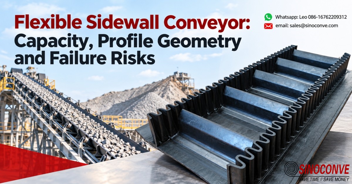
A flexible sidewall conveyor is a flat base belt with a corrugated rubber wall bonded along each edge, plus rubber crossbars called cleats vulcanized between those walls at a fixed pitch. Wall and cleats together form a moving pocket, and that pocket is what carries the load on inclines where a troughed belt would spill. Two numbers decide whether the installation works: the usable volume inside one pocket, and the strain that same pocket puts into the bond line at the foot of the wall. Get either wrong and the belt looks perfect on the drawing while the site replaces it twice a year.
We build sidewall, cleated and patterned belts in Ningbo for quarries, cement lines, ports and aggregate yards, and as a conveyor belt manufacturer we have sat through the same argument on dozens of sites. Somebody asks for a taller wall because the belt is spilling. Most of the time the real fault sits upstream, in the feed chute, the belt speed, or the moisture hanging in the material.
What follows is the arithmetic we run when a customer sends us a route sketch, then the profile geometry that decides how much of that capacity is physically reachable, then the failures we keep pulling off machines, and finally the measurements that settle acceptance at goods-in.

01Why a Sidewall System Wins on Short, Steep Routes
Sidewall belts cost more per meter than flat belts, so the justification has to come out of the route geometry rather than the tonnage. A quarry we quoted in 2026 needed 220 t/h lifted 30 m from a primary crusher discharge to a stockpile, and the available footprint was tight. At 45 degrees that lift needs roughly 43 m of belt center distance. A conventional troughed belt capped at a 20 degree incline would have needed about 88 m of structure, plus a transfer point, a second drive, a second take-up, and a second control panel. One machine against three.
That comparison is why sidewall installations cluster on short, steep lifts, and it is also why so many of them end up clustering in trouble.
None of this makes the wall a capacity booster. On a horizontal run, a 1000 mm troughed belt moving at 1.2 m/s will out-carry any sidewall belt of the same width. What the corrugated wall buys is angle, and angle only pays when the alternative is a transfer tower and the civils that come with it.
What the Corrugated Wall Changes About Route Layout
Material resting on a flat or troughed belt is held in place by friction, so the maximum working incline follows the friction angle between rubber and bulk solid, with the natural slope of the material setting the practical ceiling. Put a corrugated wall down each edge and the load no longer depends on friction for its support. It sits in a pocket, walled on two sides and re-supported by a cleat every few hundred millimeters. That is the whole trick, and it is why a vertical lift is mechanically ordinary once the pocket is defined.
Nothing about the arrangement is free. Each cleat interrupts the belt surface, each wall stiffens the edge zone, and both pass over every pulley twice per revolution.
The design problem is therefore to keep that cycle gentle enough that the rubber survives it for the 20,000 to 30,000 hours a mine or cement plant expects from a main conveyor.
Field note from our engineers: On a 42 degree clinker route in eastern China, a maintenance team fitted a 160 mm sidewall where the original drawing called for 120 mm, because the first belt was spilling at the transfer. The spill did not change. Moving the skirt rubber 200 mm further down the chute fixed it that week. All the taller wall accomplished was adding mass above the belt line and a heavier bending moment at the root, which is where the next failure appeared eleven months later.
02What a Flexible Trough Is Made Of, and What Each Part Carries
A sidewall belt leaves the press as one vulcanized assembly rather than a kit of parts, with base belt, corrugated wall and cleats bonded hot in a single cycle so the finished article behaves as a homogeneous member over a pulley. Buyers sometimes ask whether the wall can be glued on later to save freight or allow field modification. As a conveyor belt supplier working with quarries and cement plants daily, we refuse, because cold-bonded walls peel at the feather edge within a few thousand cycles.
| Element of the assembly and the job it does | Work it performs on a running machine | Failure signature we look for first |
|---|---|---|
| The base belt carries the full tensile load of the conveyor and takes every flex cycle over the pulleys and idlers. | It resists the belt tension, transmits drive force and holds the transverse stiffness that keeps the pocket from buckling sideways. | Edge scuffing and ply separation just outside the wall base, usually where tracking has been poor for months. |
| The corrugated wall stands vertical on each edge and confines the bulk solid at whatever angle the route demands. | It converts an open belt surface into a closed trough and absorbs the outward pressure of the material column inside it. | Cracks running along the bond line at the wall root, opening wider on the pulley side of the belt. |
| The cleats cross the belt at fixed intervals and turn a continuous surface into discrete pockets. | They support the material column against gravity on the incline and set how much product each pocket can hold. | Torn or missing cleats near the loading zone, often accompanied by a groove worn into the skirt rubber. |
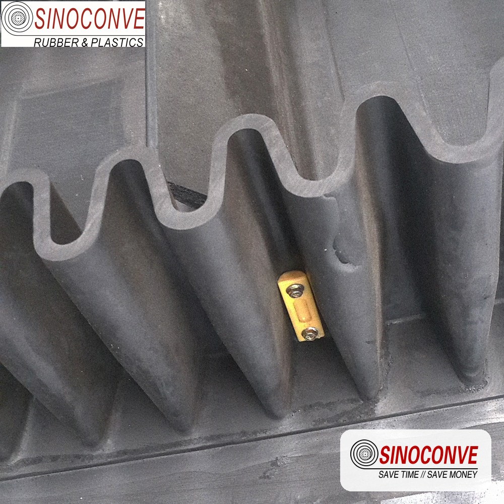
Wall, cleat and base belt cured as one assembly, with the wall base sitting inside the flat zone of the carcass.
03Pocket Capacity: Working the Effective Cross-Section Yourself
Capacity arguments are settled with a calculator, not with opinions. Anyone quoting an industrial conveyor belt for a steep lift should be able to show the pocket arithmetic in full, because the same numbers also tell you whether the cleats will hold.
The Geometric Volume Inside One Pocket
Start with the flat plate of belt between the wall bases, since that is the only area that actually fills. A 1000 mm belt carrying a hot-vulcanized wall with an 80 mm base on each side leaves 840 mm of usable width. Set the cleat height at 100 mm and the pitch at 300 mm, and the pocket envelope is 0.84 m times 0.10 m times 0.30 m, which comes to 0.0252 m³ of space per pocket before anything is subtracted.
Material never fills that envelope completely. Angular crushed limestone at a 6 percent moisture content leaves roughly 70 percent of the envelope occupied once you allow for the natural slope of the load and the space lost against the cleat face, so one pocket holds about 0.0176 m³. At a belt speed of 1.2 m/s and a 300 mm pitch, 4.0 pockets pass the discharge lip every second. That gives 0.0706 m³ per second, or 254 m³ per hour, and at a bulk density of 1.4 t/m³ the geometric figure is 356 t/h.
Turning Geometric Volume Into a Tonnage You Can Trust
Geometric tonnage is not the number to put on a drive datasheet. On a 45 degree incline, some of the material sitting on the cleat face slides back over the preceding cleat during the climb, and the amount lost depends on wall height, pitch, particle size and moisture. Our field correction on that configuration is a retention factor of about 0.75, which brings 356 t/h down to 267 t/h. That is what we would quote, and it is the figure the drive, the take-up and the structure should be sized against.
One more check before the drawing is signed off. Each full pocket holds about 24.6 kg of material. Working out the gravity component along the incline at 45 degrees gives roughly 171 N of sliding force per pocket, and a joint designed for the loading-zone impact should carry three times that, so about 510 N at the cleat base.
Field note from our engineers: The 267 t/h figure above is not a derating factor invented for this page. On a limestone installation in Zhejiang we first measured the pocket fill visually through an inspection hatch, timed 40 pockets, then weighed the discharge over a two-minute window. The weighed output came in within 3 percent of the derated calculation and 21 percent below the geometric number the original supplier had quoted.
04Profile Geometry: Corrugation Heights and the Base Belt They Demand
Corrugation height is the single most consequential dimension on the drawing, because it simultaneously sets capacity, root stress and the pulley diameter the installation will need. Taller walls are not a free upgrade. A rubber conveyor belt carrying a 160 mm wall needs a base with enough transverse rigidity to hold that wall upright, and enough thickness under the wall base that the bond does not tear out on the first cold start.
W-type corrugation leaves the press with a wave period that lets it compress on the inside of a bend and open on the outside, which is how the wall survives going around a pulley at all. Height, wave period and base width travel together as a matched set. A 120 mm wall wants a corrugation base around 80 mm wide on a four-ply EP carcass, and the wall is compounded to stay flexible at the lowest temperature the site will actually see rather than the one on the enquiry sheet.
| Corrugation height we normally see in service | Base belt construction that suits this wall height | Smallest pulley diameter we will accept at quote stage | Duty where this height band fits comfortably |
|---|---|---|---|
| 40 mm up to 60 mm, used on light and medium pocket work | Two or three ply EP carcass with a standard abrasion resistant cover grade | 500 mm to 630 mm, which keeps root strain inside a comfortable band | Small aggregate, sand, fertilizer and packaged bulk on short inclined runs |
| 80 mm up to 120 mm, the workhorse range across our order book | Three or four ply EP carcass with extra transverse stiffness under the wall base | 800 mm to 1250 mm depending on ply count and total belt thickness | Quarry feed, cement clinker, crushed stone and most mobile crushing spreads |
| 160 mm up to 200 mm, seen on heavy ore and port installations | Four or five ply EP or NN carcass built specifically for steep angle pockets | 1250 mm to 1600 mm, and we would rather add diameter than accept more | Iron ore, bauxite, heavy lump feed and port bulk transfer towers |
| 250 mm up to 400 mm, reserved for genuinely difficult vertical lifts | Five or six ply heavy EP or a steel cord base where tension demand is extreme | 1600 mm to 2000 mm, and the pulley usually drives the whole layout | Roasting plant feed, sinter, and vertical lifts inside confined structures |
Every row in that table carries the same warning. Sidewall height should stay below roughly one tenth of the pulley diameter the belt has to run over. Break that ratio and the wall root is asked to bend through a radius it was never compounded for.
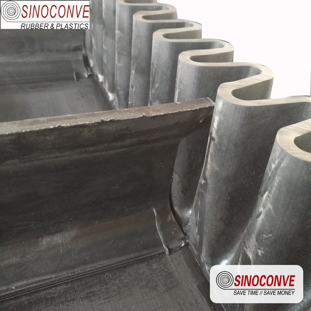
Wave period, wall height and cleat height are chosen together on the drawing, because changing any one of the three shifts both the pocket volume and the bending strain at the root.
05Cleat Profiles and Pitch: the Dimension That Sets Wear Rate
Cleats do two jobs at once. They divide the belt into pockets, and they carry the weight of the material column that would otherwise slide back down the incline. Both functions depend on how far apart the cleats sit, and pitch is the dimension buyers change most often without understanding the consequence.
T, S and C Profiles and Where Each One Belongs
The three cleat families we tool share a common logic. A T profile has straight flanks and a flat top, and it suits aggregate, clinker and most mineral duties where material flows freely and wears moderately. An S profile carries a relieved flank so a heavier cleat flexes with the belt instead of fighting it, which matters on small pulleys and on reversing belts. A C profile sets a curved, wider base under a heavy body and spreads peel load across more bond area.
Face height works alongside shape. A cleat that is too short lets material roll over its top between pockets, while one that is too tall adds mass and rotating inertia for no capacity gain, since the usable depth is set by the wall.
Pitch then decides how often the load is re-supported. On a 45 degree route with 100 mm cleats, 300 mm pitch is a reasonable starting point, and the practical envelope runs from about 1.5 to 3 times cleat height. Go steeper than 60 degrees with a wet or cohesive material and the pitch should shorten toward the lower end, because a long unsupported span lets the material slump forward against the next cleat and load it unevenly. Where a project also needs a drive for the feeder or the stacker, the belt can come from the same plant as the drive, because the workshop that builds these pockets also builds rubber and cogged drive belts, which means a question meant for a transmission belt manufacturer usually lands on the same engineer in the same week.
Teams that also have to source wrapped and raw edge cogged profiles for the crusher drives upstream of these conveyors deal with a V-belt manufacturer from the same building, and the two product lines meet more often than people expect on a mobile crushing spread.
06Matching Wall and Cleat to Belt Construction and Ply Count
A sidewall belt is not a standard carcass with rubber added on top. The wall base has to sit over a zone of the carcass that will not stretch away from it, and the cleat peel load has to be spread across enough fabric to keep the bond line in compression rather than peeling it open. That is why ply count climbs faster on a sidewall belt than tension alone would require.
Why Extra Plies Buy More Than Strength
For a 1000 mm wide belt carrying a 100 mm wall and a 300 mm cleat pitch, three plies is the practical floor and four is what we usually recommend. The extra ply is not there to carry more tonnes. It is there to hold the wall base flat under load, to raise the transverse stiffness of the belt so the pocket does not concertina sideways between the idlers, and to give the cleat bond enough substrate to fail slowly instead of instantly. Buyers negotiating on wholesale conveyor belts frequently try to drop a ply to hold a budget, and that is the wrong place to economize.
Two more construction details travel with the ply decision. The belt needs an edge margin of roughly 40 to 60 mm outside each wall base, so the wall never sits on the radius where the belt starts to curve. And the carcass should be a fabric construction rather than a steel cord design unless tension demand is extreme, because fabric tolerates the repeated local bending at the wall root far better.
07Design Criteria: Inclination Angle Against Moisture and Stickiness
How Far Each Angle Band Will Realistically Go
Dry, free flowing aggregate up to 10 mm in size will ride a 60 to 100 mm wall at 30 to 45 degrees all day. Move to 45 to 60 degrees and the wall should go to 120 mm with a pitch shortened toward 250 mm, because the period the material spends unsupported grows with the steeper climb. Above 60 degrees the pocket is doing nearly all the work, and wall height and pitch both need to be sized from the material rather than from the drawing template.
Vertical lifts to 90 degrees are technically ordinary once the pocket is right, but they deserve a warning. A vertical run puts the full material column onto the cleats in pure shear, and any material that sticks to the belt face will be carried past the discharge lip and down the return strand.
What Moisture and Cohesion Do to the Pocket
Surface moisture is the more dangerous of the two. Free water on particle surfaces acts as a lubricant between the bulk solid and the rubber, so a quarry that handles 4 percent moisture limestone without trouble can start losing its pocket at 9 percent after a wet week. Clay bearing material behaves differently again, because it has its own cohesion and will hold a vertical face inside the pocket but then refuse to release at the discharge point.
Our rule of thumb is that material carrying more than about 8 percent surface moisture should not be specified at the same angle as the dry version. Either the wall grows, the pitch shortens, or the angle comes down. Material that packs into a solid lump is worse still, and we would rather see it shear tested than guessed at.
One field test costs nothing and settles more arguments than any data sheet. Fill a sample box with the actual material at the working moisture content, turn it to the working angle, and watch it for ten minutes. If the face slumps or a gap opens under the cleat, the specification has to change before the belt is built. A conveyor belt distributor holding sample material on the shelf can often answer that question in an afternoon.
08When to Change the Feed Instead of Deepening the Wall
Roughly one in three spill complaints we investigate has nothing to do with the belt. The material is being delivered wrong, and the pocket cannot fix a loading problem it never had a chance to solve.
Symptoms That Point Upstream of the Belt
Spill concentrated at the loading point rather than along the incline is the clearest signal. So is spill that only appears when the feed rate peaks, or when the second truck dumps. If the material lands on one side of the belt because the chute has shifted, tracking suffers before capacity does, and the wall on the loaded side wears twice as fast as the other one.
Check the belt speed against the feed first. A 1.6 m/s belt fed by a chute designed for 1.0 m/s throws material against the wall instead of settling into the pocket, and dust escapes through every gap in the skirt. Dropping the speed by 0.3 m/s often removes more spill than 40 mm of extra wall, and it costs nothing but a pulley change.
Placing the load centrally also depends on chute geometry rather than on belt selection, and this is where site visits beat email. Anyone who has walked through a conveyor belt factory and watched a belt being press cured tends to take the loading zone more seriously once the machine is on their own ground.
09Failure Risk One: Cracking at the Sidewall Root
The wall root is where a sidewall belt fails first, and it is almost always a bending problem rather than a rubber quality problem. The wall stands on a base about 80 mm wide, bonded to a carcass that is stiff in the longitudinal direction and quite willing to resist any shape change it is asked to make. Every time the assembly passes over a pulley, the carrying surface sits on the outside of the curve, and the wall base is pulled open across that radius.
Reading a Root Crack Before It Reaches the Carcass
Cracks begin as a hairline in the feather edge where the wall base meets the cover rubber, and they are easy to miss. Log them by length and depth every 500 running hours. On an over-driven installation a typical crack grows from a few millimeters at 2,000 hours to 200 mm by 8,000 hours, and once it reaches the first ply there is no repair worth doing.
Four causes account for nearly every case we open. The pulley is too small for the wall height, the belt is over-tensioned because the drive is fighting a soft start, the installation reverses and gives the wall root an extra bend, or the belt was clamped and force fitted and the root was creased before it ever ran. On a quarry installation in Hebei the cracks traced back to a take-up set 40 mm short of the correct stroke after a splice, pushing carry-side tension up by roughly 12 percent.
10Failure Risk Two: Corrugation Fatigue and Cold Weather
A corrugated wall is a flexing structure with a very large number of cycles ahead of it. Take a 1000 mm belt on a 1250 mm head pulley, running at 1.2 m/s. The pulley circumference is about 3.93 m, so the belt makes roughly 1,100 passes over the head pulley every hour, and something close to 2,200 full flex cycles per hour when the tail pulley is counted. Over a 7,200 hour year that is on the order of 15 million cycles through the corrugation.
Rubber handles that count comfortably when it is warm and when the wall is the right height for the pulley. It handles it badly when the compound is stiff.
Why Cold Starts Cost More Than Cold Running
Low temperature stiffens every elastomer, and the effect on a corrugated wall is larger than on a flat belt because the wall is asked to bend through a much tighter local radius. A compound that performs well at 20 degrees C can behave quite differently at minus 25 degrees C, where the flexural modulus rises sharply and a cold start puts the first big strain into a material with no flexibility left to give.
For installations that see sustained sub-zero conditions we specify a low temperature grade and ask for a bend test at the site minimum rather than a nominal figure on a data sheet. Northern Chinese and Central Asian sites also tend to run a warm-up cycle before loading, which is a cheap habit that adds years to a corrugation.
Two failure signatures belong to this cause rather than to root cracking. The first is a crack running across the wave crest on the outside of the bend, usually beginning on the strand that has the longest unsupported span. The second is a whitish chalky band along the same line, which is the rubber telling you it has been bending below its glass transition region for a while.
11Failure Risk Three: Cleat Tear-Off, Bond Failure and Splices
Cleats come off for three reasons, and only one of them is a rubber failure. The other two are a bolted fixing that was never appropriate, and a splice that was laid out without thinking about the cleat grid.
Bolted, Cold Bonded or Hot Vulcanized
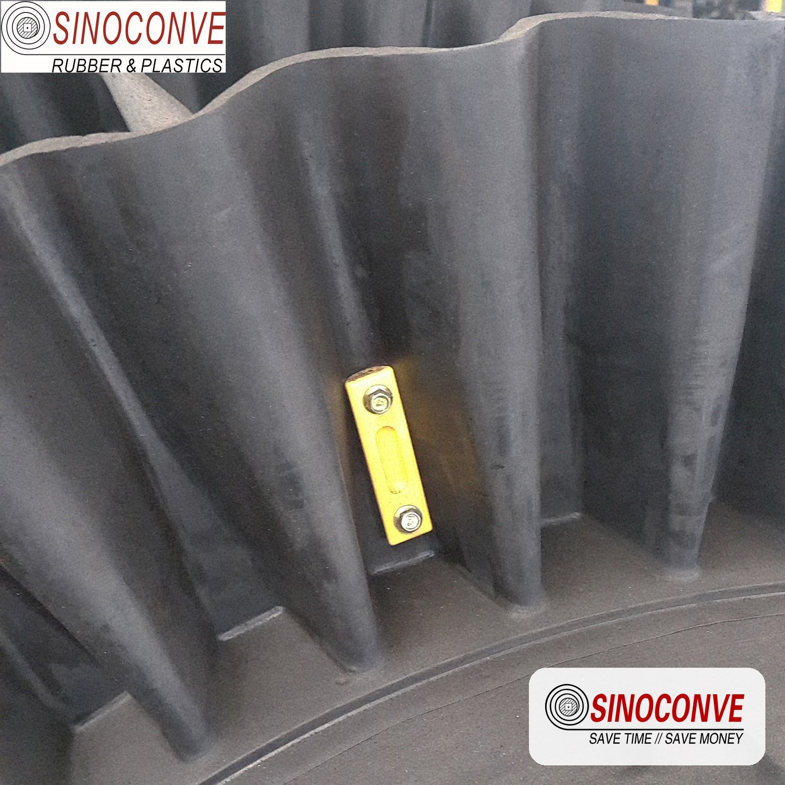
Field-bolted cleats are common on retrofit projects because they avoid a press. They also create a hole through the belt, which introduces a water path into the carcass and a stress raiser exactly where bending strain peaks. A bolted cleat on a 45 degree route with 24 kg of material pushing against it will elongate its holes within a few months, and the belt then begins to leak material through the fixing rather than failing outright, which is the harder problem to notice.
Hot vulcanization during manufacture is the only method we will put a warranty behind. The bond is formed under heat and pressure against a prepared cushion, so the wall and the cleats are chemically continuous with the base belt cover rather than stuck to it. Field replacement of an individual cleat is possible with a portable press and uncured bonding gum, but the bond face has to be ground back to sound rubber first, and a cleat re-bonded over an oxidized surface will outlast the shift and not the month.
Laying Out the Splice Around the Cleat Grid
Splice layout is where a good belt gets ruined by a rushed installation. Two rules matter. Never let a cleat sit on or beside the splice within about 150 mm, because the splice zone is slightly thicker and stiffer and the cleat will lift at its edge. Keep the cleat pitch continuous across the joint, so the material sees an even pocket rhythm instead of one long gap that gathers a surge of load.
The wall splice should also be staggered from the base belt splice rather than stacked on top of it. Stacked and the joint becomes a stiff plate that refuses to bend over the pulley, which is precisely how a corrugation starts cracking on a belt that is otherwise healthy. A lap splice of the belt itself, hot cured in the field, is normally expected to retain a large majority of the belt's rated tensile strength, with figures in the region of 80 to 90 percent commonly quoted by belt makers.
| Failure signature you find on an inspection walk | Mechanism that produced the damage in the field | Action that actually removes the cause |
|---|---|---|
| Hairline cracks opening along the foot of the wall, worst on the pulley side | Repeated bending through a radius that is too tight for the wall height | Increase pulley diameter, reduce take-up tension, or lower the wall height |
| Chalky white band or a split across the wave crest of the corrugation | Flex fatigue with the compound running below its low temperature limit | Specify a low temperature grade and introduce a warm-up cycle before loading |
| Cleat lifted clean off the belt with rubber still attached to both faces | Impact from lump feed inside the loading zone, combined with too long a pitch | Shorten the pitch, lower the drop height, or shift the first cleat clear of impact |
| Belt pulled apart at the joint while the rest of the carcass is undamaged | A cold bonded or badly prepared splice carrying full running tension | Re-cut and hot cure the splice, then verify with a pull test on a coupon |
12Return Side: Carryback, Rollback and Cleaner Interference
The return strand of a sidewall conveyor is the part of the design nobody draws carefully and everybody curses later. Standard cleaning equipment is built for a flat belt face, and a belt with a 120 mm wall standing on each edge and cleats crossing it every 300 mm is not that.
Cleaning a Surface That Has Walls and Cleats On It
A single full-width scraper blade under the head pulley will be destroyed within a shift, because the wall arrives 120 mm proud of the belt face and the blade has nowhere to go. Segmented blades can sit in the gaps between cleats and between the walls, provided the pitch was chosen with cleaning in mind. A rotary brush tolerates the wall because it flexes. A plough carries released material off to one side before it reaches the tail, and the wider question of when a scraper stops being the right tool is covered in our notes on cleaning methods and schedules for conveyor belts.
Whichever is chosen, the material that sticks inside the pocket is the real enemy. Carryback on a sidewall belt usually rides in the corner between the wall base and the belt face, and it accumulates until a lump drops onto the return idlers. Angled or v-shaped return idlers then track the belt badly, which is how the edge damage in the earlier table starts.
Rollback: the Load You Forgot Was Sitting There
Every loaded incline conveyor carries potential energy in the material column, and a sidewall belt can carry more of it at a steeper angle than any flat belt. Take the earlier example: 0.082 t of material sits on every meter of a 1000 mm belt running at 1.2 m/s and 267 t/h, so a 43 m inclined section holds about 3.5 t of limestone. Released down a 45 degree slope, that mass produces roughly 24.6 kN of force pulling the belt backward.
A backstop or a brake sized for the flat belt that used to be installed is not automatically adequate for that figure, and a conveyor that rolls back does immediate damage. Material is dragged into the tail, the pocket jams solid against the skirt, and cleats tear off in sequence rather than one at a time. We have also seen the same event shear the wall from the belt along several meters.
Two habits prevent it. Verify the hold-back rating against the fully loaded inclined mass, not against the drive rating. And arrange the return idlers so the wall has clearance, because a corrugation crushed between a roller and the belt is a wall that has to be replaced in the field.
| Problem seen on the return strand | Why a standard conveyor arrangement does not fit | Arrangement that works on a sidewall belt |
|---|---|---|
| Cleaning blade shattered or bent within the first operating shift | The wall stands far above the belt face and the blade cannot pass it | Segmented blades in the pockets, a rotary brush, or a diagonal plough |
| Material rolling back into the tail and jamming the pocket solid | Hold-back equipment sized from the drive rather than from the loaded incline | Check the backstop against the full inclined mass and add a brake where needed |
| Corrugation squashed flat along part of the return run | Three roll troughing idlers support a surface that is no longer flat | Flat return rollers under the center with clearance left for both walls |
| Belt tracking away to one side after a few weeks of running | Carryback falls unevenly on one wall and pulls that side down onto the rollers | Improve discharge release first, then re-align tracking on a clean belt |
13Procurement and Acceptance: What to Measure Before the Belt Ships
Most sidewall belt disputes are settled by measurement rather than by argument, and the measurements are cheap. A tape, a caliper, a straight edge and a pull test coupon will cover almost everything that decides whether the belt lives up to the order.
The Six Checks That Catch Almost Everything
Sidewall height tolerance is the first one, and it is routinely missed. On a nominal 120 mm wall we work to a tolerance of about plus or minus 3 mm, measured at several points along the length, because a wall that varies more than that changes the pocket volume along the belt and loads the drive unevenly. Cleat pitch should hold within about 5 mm of nominal across the full length, and cleat height within 2 mm, since pitch error accumulates into one long gap that gathers material.
Bond strength is the check that separates a good belt from one that will be back in three months. Take a section of finished belt with wall and cleat still attached and pull the wall off the base in a peel test until it separates. What matters is the mode of failure as much as the number. Rubber should be left torn on both faces.
Rubber grade verification then follows the customer's own specification, and our abrasion resistance guide for quarry conveying explains how those grades behave in practice. Abrasion loss to DIN 53516 in the region of 90 to 150 mm³ is typical for a good quality quarry cover, cover grades are commonly specified against DIN 22102 or RMA Grade I and II practice, and flame resistance for underground coal duty should be evidenced against the applicable standard rather than asserted in an email.
| What to verify before the belt ships | How a buyer can confirm it on arrival | The result we would expect on a compliant belt |
|---|---|---|
| Sidewall height and the straightness of the wall line along the belt | Measure the wall at five points with a caliper and lay a string along the edge | Height within a few millimeters of nominal and a wall with no visible waviness |
| Peel strength of the wall to base bond and the cleat to base bond | Cut a sample from the belt end and pull the wall off in a bench vice | Rubber torn on both faces rather than a clean separation from the base |
| Cover compound grade, abrasion class and flame performance if applicable | Read the mill certificate against the purchase specification line by line | A certificate that names the compound and cites the test method used |
| Low temperature flexibility where the site sees genuine winter conditions | Ask for a bend test result at the lowest temperature on the site record | A test temperature below the site minimum, not merely below zero |
| Cleat pitch uniformity across the whole length including the splice area | Walk the belt and measure every pitch, marking any value that is out | Uniform pitch with no long gap, and no cleat close to the splice |
| Splice construction and the strength it retains in the finished belt | Inspect the joint area for cold bonding and request a coupon pull test | A hot cured joint with wall and cleats re-bonded under proper pressure |
Two refusals belong on every purchase order. Do not accept a sidewall belt whose wall or cleats were attached with room temperature adhesive, and do not accept one where a cleat sits within about 150 mm of the splice. Both decisions are invisible on a delivery note and extremely visible eight months into service.
14Flexible Sidewall or Standard Patterned Belt?
The boundary between the two is simpler than the marketing suggests. A patterned belt with raised bars relies on form friction between rubber and bulk solid, it stays open across its width, and it normally works somewhere between 15 and 30 degrees on a route that has the length to accept that angle. A flexible sidewall belt closes the trough with walls and holds the load in mechanical pockets, which is why it reaches from 45 degrees all the way to vertical without losing its contents.
Where the Two Overlap in Practice
Overlap happens between 25 and 35 degrees, and there the choice comes down to route length rather than to the belt itself. A short, steep transfer squeezed into an existing building usually wants the pocket, while a long overland conveyor climbing the same 30 degrees almost always wants the patterned belt.
If a route sketch is on your desk and the incline is awkward, send it across. We will run the pocket arithmetic, check the cleat load against the material, and tell you plainly whether the wall is the right answer or whether the feed chute is.

15Frequently Asked Questions
Is a flexible sidewall conveyor the same thing as a chevron belt?
No. A chevron belt is an open belt with raised bars that rely on form friction, while a flexible sidewall conveyor uses bonded corrugated walls and cleats to form closed pockets, which is what allows the much steeper angle.
How do I calculate the capacity of a sidewall conveyor?
Multiply the usable belt width between the wall bases by the cleat height, then by the cleat pitch, to get the volume of one pocket envelope. Derate that envelope for the fill the material actually achieves, which is typically 65 to 75 percent for crushed aggregate, and multiply by the number of pockets that pass per second at the working belt speed. Convert the volume flow with the bulk density and you have a geometric tonnage. Cut the result by a retention factor for the working angle, in the region of 0.75 at 45 degrees for typical crushed stone, and only then quote it.
What sidewall height suits a 45 degree incline?
For aggregate and clinker duty, a wall between 80 mm and 120 mm with a cleat pitch near 300 mm handles most 45 degree routes. Material that is wet, fine or cohesive needs the taller end of that range with a shorter pitch, since it has less internal stability and will slump toward the next cleat. Anything carrying lump feed at high tonnage should be checked on the pocket volume rather than copied from a similar installation, because the fill factor falls quickly as particle size grows.
Why does my sidewall belt crack at the base of the wall?
The wall root is being bent through a radius that is too tight for its height, which usually traces back to a pulley smaller than the wall demands. Over-tensioned take-up adjustment makes it worse by adding tensile strain on top of the bending strain. Log crack length every 500 running hours and stop repairing once the first ply is exposed, because a root crack that reaches the carcass cannot be recovered in the field.
Can a damaged cleat be replaced on site?
It can, provided the crew grinds back to sound rubber and uses a portable press with uncured bonding gum rather than an adhesive. A cleat bonded over an oxidized or dusty face will hold for a few weeks and then come away again, usually somewhere less convenient.
How tall can a corrugated sidewall be?
Commercially we supply corrugated walls from about 40 mm up to 400 mm, and the practical ceiling on any given machine is set by the pulley diameter, which we like to keep at least ten times the wall height.
Do I need special return idlers for a sidewall belt?
Yes, and this is one of the most common conversion mistakes. Standard three roll troughing idlers press on a surface that now has walls standing 100 mm or more proud of the belt face, so the corrugation gets crushed along part of the return run. Flat rollers positioned under the flat center of the belt, with clearance left for both walls, avoid the problem. Poor carryback makes any roller arrangement worse, and the return side belt cleaning routine matters more on a pocket belt than on a flat one because material lodges in the wall corner.
What height tolerance should I accept on a corrugated wall?
On a 120 mm sidewall we work to about plus or minus 3 mm, measured at several points along the belt, and we would question anything outside plus or minus 5 mm. Height variation changes the pocket volume from one section to the next, so the discharge rate drifts with it. A wavy wall line also points to a base that was not held flat during cure, and that is a fair predictor of early root cracking. Check the figure on arrival rather than after the belt is spliced and threaded.
At what temperature does a sidewall belt stop working?
There is no single figure, because it depends on the compound rather than on the belt type, but a standard natural rubber sidewall becomes noticeably stiff well before minus 20 degrees C while a low temperature grade keeps usable flexibility further down, and the difference shows up first in the corrugation rather than in the base belt.
Whichever belt type sits on your route, the failure pattern is nearly always decided in the first few meters after the loading point and at the wall root over the pulleys. Watch those two zones, keep the arithmetic honest, and a sidewall installation will outlast the flat belt it replaced by a wide margin. Browsing our cover grade comparison is a reasonable next step if rubber selection is still open, and the conveyor belt splicing guide covers what happens when the joint is not planned around the cleat grid.
Related Products You May Need
- Rubber conveyor belt for the general purpose duties behind most sidewall enquiries
- EP rubber conveyor belt where carcass strength and low stretch matter on long inclined runs
- Chevron conveyor belt when the incline sits inside the angle range a patterned surface can hold
- Heat resistant conveyor belt for clinker, sinter and cement duties that also run steep
- Steel cord conveyor belt for high tension main lines feeding the inclined section
- Conveyor rollers and return idlers selected to clear a corrugated wall
- Full product catalog covering fabric, steel cord, patterned, sidewall and light duty belts
Related Blog Posts
- Abrasion resistant conveyor belt guide for quarry and steep angle conveying
- Return side belt cleaning on inclined and pocket belt installations
- Conveyor belt cleaning methods, schedules and when scrapers will not work
- Conveyor roller ultimate guide 2026 for idler and return roller selection
- Quarry crusher conveyor belt selection for the loading zone feeding the incline
- Impact roller selection for loading zones where lump feed hits the belt
- EP conveyor belt selection for stone crusher and aggregate plants