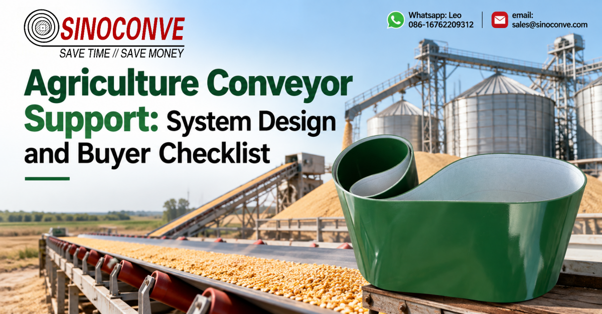

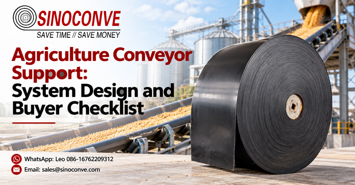
Farm conveying support is spaced from load, not from habit. On grain or produce running up to about 0.6 t/m, we set carry idlers at roughly 1.2 to 1.5 m and frame bays at 2.0 to 3.0 m, then tighten both around every loading and transfer point. On mobile or portable units the rule flips. There the limiting factor is frame stiffness under wind and uneven ground, so you reduce support spacing before you ever increase belt tension. What follows is the working set we hand to farm engineers: a spacing table, a worked load example, and a support buyer checklist you can carry to the field.
We build conveying equipment and belt at our plant in Ningbo, and a large share of the enquiries we get from farms and co-ops arrive as a photograph of a sagging frame with a load of grain drifting sideways off the belt. Very few of those calls turn out to be a belt problem. They turn out to be a spacing problem, a bearing problem, or a frame that was never sized for the load it now carries. So this page deals with the steel and the structure underneath: idlers, rollers, bays, foundations, access, and the numbers that decide each of them.

Structure is the part of a farm conveyor that nobody photographs while it works. It is also the part that settles most of the arguments, because a belt asked to bridge an unsupported span will fail at the splice long before the cover wears through. As a conveyor belt manufacturer we are usually called in after the belt has already been blamed, and the measurement that ends the discussion is almost always a sag figure taken under a known load.
One boundary before the tables. This article is about support and structure on an agricultural conveyor line: how far apart supports sit, what load they take, how open-air and dust conditions change them, what a portable machine permits, and how you reach them for maintenance. It is not a belt selection primer. If you are still deciding which belt suits a farm line in the first place, read the existing guide on farm belt selection and come back here for the steel.
01What "Support" Covers on a Farm Conveyor
Ask five people on a farm what the support system is and you will get five answers, most of them incomplete. One will say the legs. Another will say the frame. The maintainer will say the rollers, because those are what he greases on a Saturday. The support system is all of it, and it has one job: hold the belt at the right shape and the right height so the material rides on it without spilling and without dragging.
The table below is the scope map we use the first time we walk a farm line. Each row is a component family, what it is there to do, what happens when it fails, and where the first sign shows up. If a site cannot fill all four columns for its own line, that is the audit, done before any belt is discussed.
| Component | Duty | Failure Consequence | Inspection Point |
|---|---|---|---|
| Carry idlers | Hold the loaded belt at the designed trough shape | Belt sag, spillage, edge wear, splice fatigue | Top face of each idler, at mid-bay |
| Return rollers | Carry the empty belt on the return run | Belt drag, higher power draw, top-cover polish and wear | Return run, either side of any low point |
| Impact idlers at the feed | Absorb drop energy where material lands | Belt puncture, frame shock, bearing collapse | Directly under the chute skirt, two bays each side |
| Frame stringers | Carry idler loads back to the legs | Progressive sag, bolt elongation, misalignment | Bolt rows, every second bay |
| Truss or long bay | Span a distance with no intermediate leg | Bending, wind flex, resonance at running speed | Mid-span of the longest unsupported bay |
| Transition idlers | Shape the belt from flat to the trough angle | Edge stretch, tracking drift, permanent belt cupping | Both ends of every trough transition |
| Pulley and bearing supports | Take full belt tension and pass it to ground | Shaft deflection, bearing heat, sudden seizure | Bearing housings, drive and tail ends |
| Take-up frame | Hold tension and allow adjustment over time | Slipping drive, splice pull-out, tracking loss | Travel remaining on the take-up screws |
| Portable undercarriage | Keep the frame rigid while the machine is moved | Twist, leg sinking, belt running off-centre on soft ground | Legs and pin joints after every move |
We keep a product catalog of the roller and frame hardware that goes under a farm line, because most sites end up replacing the support in sections over a few seasons rather than in one clean rebuild.
The three questions that fix a support design
Every support layout we have ever signed off came down to three inputs. What is the worst load per metre the belt will ever carry, not the average. How long a span can the frame tolerate before deflection becomes a tracking problem. And what does the site actually allow underneath, meaning legs, anchors and a maintenance walk. Answer those three and the spacing table writes itself. Get any one of them from a memory instead of a drawing and you will be repairing a frame next harvest.
What support is not there for
Support does not tension the belt, and it cannot compensate for a belt that is too stiff for the trough it runs in. We have watched crews raise frames and shim idlers to chase a tracking fault that lived entirely in the belt construction. Support sets geometry. Tension sets grip. Confusing the two burns a day of labour and usually makes the fault worse.
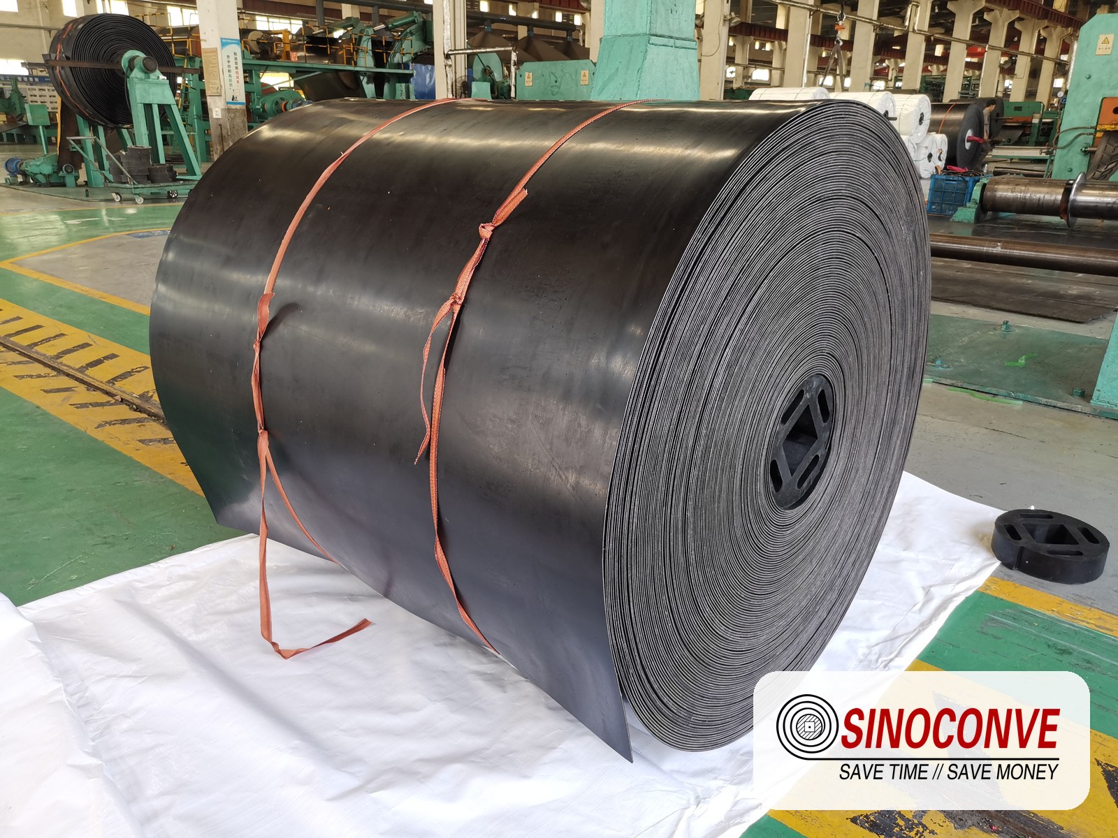
Carry idlers set out along a farm line; spacing here is the first thing we measure on a site visit.
02Idler and Roller Spacing for Agricultural Loads
Spacing follows load, and load on a farm line changes more than most designers expect. A conveyor that carries light grain for ten months can see wet root crop or soil-laden produce in the same trough for three weeks. We size the support for the heavier figure and let the light season run under-stressed, because over-supporting a farm line costs a fraction of what one under-supported harvest costs in lost material and patched splices.
The spacing table below is the starting point we use for flat and troughed farm belts up to about 1.2 m wide. Carry spacing is the distance between successive carry idler stations. Frame bay is the structural bay between leg frames. Loading-zone spacing is the tighter value we force near any feed point, where the belt absorbs drop energy as well as steady load. The three numbers are deliberately different, and they matter most exactly where people simplify them.
| Load (t/m) | Carry Spacing | Frame Bay | Loading Zone Spacing | Typical Duty |
|---|---|---|---|---|
| up to 0.3 | 1.5 to 1.8 m | 3.0 to 3.6 m | 0.9 to 1.2 m | Light produce, sorting and inspection runs |
| 0.3 to 0.6 | 1.2 to 1.5 m | 2.4 to 3.0 m | 0.8 to 1.0 m | Dry grain, seed, chaff, standard silage |
| 0.6 to 1.0 | 1.0 to 1.2 m | 2.0 to 2.4 m | 0.6 to 0.8 m | Wet root crop, dense forage, wet silage |
| 1.0 to 1.5 | 0.8 to 1.0 m | 1.6 to 2.0 m | 0.5 to 0.6 m | Soil-laden crop, heavy wet lines, short spans |
| over 1.5 | 0.6 to 0.8 m | 1.2 to 1.6 m | 0.4 to 0.5 m | Heavy-duty only; check the frame before the belt |
Two design notes sit behind those numbers. First, the loading-zone figure is not just tighter spacing, it is usually a different idler with a heavier bearing and an impact-rated roll. Second, the return run needs its own look, because on a farm line the return rollers are often the first to seize and the hardest to see. A farm line that runs a rubber conveyor belt over wet soil has one extra reason to check the return side: the belt top cover carries moisture back into the trough, and that moisture finds the lowest bearing on the run.
Worked example: a 1.2 m bay carrying 220 t/h
Take a fixed grain line, 1.2 m wide, 35 degree trough, belt speed 2.0 m/s, carrying dry wheat at a bulk density of 0.78 t/m3. The site wants 220 t/h. The loaded cross-section works out at A = 220 / (3600 x 2.0 x 0.78) = 0.039 m2, which gives a distributed load of about 0.031 t/m, or 31 kg for every metre of belt. At a 1.2 m carry spacing that is 37 kg sitting on each idler station. A 37 kg station sounds trivial, and it is, until you remember that the same belt will run wet root crop in a wet autumn and that a feed chute drops material from height. We size the idler for the season that is not average.
Where the spacing table stops being enough
The table assumes a uniform load and a straight run. Real farm lines break both assumptions at the same three places: the feed, the discharge, and any change of direction. Tighten the spacing there and leave the middle at the table value. If you find the belt sagging between idlers in the middle of a bay, the diagnosis is not always "add idlers". Sometimes it is a frame that has lost its camber, and no amount of extra idling will straighten it. For the roller geometry itself, the conveyor idler roller guide covers roll diameter, bearing type and seal choice. We stay on spacing.
The wider context matters too, because a farm conveyor is one link in a chain that starts in a field and ends in a store. If you want the system view rather than the steel view, our agriculture industry page shows how intake, cleaning, grading and outloading lines connect, and the support rules change a little at each handover.
03Frame and Truss Spacing
A farm frame is usually lighter than a mine frame and is usually asked to do more with less. It has to span between legs that may sit on a concrete pad or on a field edge that was ploughed last week. It has to tolerate wind when it is empty, lateral impact when it is full, and the twisting that comes with a machine that gets towed from one stack to the next. Most of all it has to stay straight enough that the belt tracks, which on a 1.2 m belt means mid-span deflection staying in the low millimetres under working load.
Deflection, not stress, sets the bay size
We work to a deflection limit rather than to a stress limit on farm frames, because a frame that is strong enough but springy will run a belt off-centre long before it bends permanently. The limit is usually written as a fraction of the span, so the longer the bay, the stiffer the section has to become to meet the same relative target.
| Span | Typical Profile | Deflection Target | Where It Fits |
|---|---|---|---|
| up to 2.0 m | Single angle or channel, 60x60 to 80x80 | L/500 | Short fixed lines, crop intake tables |
| 2.0 to 3.0 m | Channel 100 or light truss | L/500 to L/600 | Standard grain and silage bays |
| 3.0 to 4.5 m | Two-chord light truss | L/600 | Fixed lines where intermediate legs are costly |
| 4.5 to 6.0 m | Braced three-chord truss | L/700 plus lateral bracing | Long fixed spans, gantry-mounted lines |
| over 6.0 m | Designed truss, not a stretched bay | Engineered per case | Rare on a farm line; consider a leg instead |
Field note from our engineers: a portable grain unit we surveyed had a frame bay of 3.5 m and a visible bow at mid-span whenever the hopper was full. The material arrived off-centre and the crew kept adding tension. We cut the bay to 2.4 m and doubled the idlers on both sides of the feed. Tracking and spillage both cleaned up inside an afternoon, and nobody touched the belt tension again.
The frame section is only half the story, and the rollers that bolt to it are the other half. Our steel conveyor rollers selection guide sets out how shell thickness and bearing class should scale with the load the bay actually carries, and as a conveyor belt factory we see the mismatch often enough to put it in writing.
04Load and Capacity Calculations
Every support decision reduces to one number: the load a single station has to carry, with a margin for the worst day. That margin is not guesswork. We build it from three parts, a static load from the material, an impact allowance for the drop at the feed, and a wet-season allowance for the fact that farm material gets heavier, not lighter, when the weather turns.
The calculation chain we run for a farm line
| Input | Value | Calculation Step | Result |
|---|---|---|---|
| Belt width | 1.2 m | Given from the line | Fixed |
| Throughput | 220 t/h | Site target | Fixed |
| Belt speed | 2.0 m/s | Drive selection | Fixed |
| Bulk density, dry wheat | 0.78 t/m3 | Material data | Fixed |
| Loaded area | 0.039 m2 | A = 220 / (3600 x 2.0 x 0.78) | 0.039 m2 |
| Distributed load | 0.031 t/m | w = area x density | 31 kg per metre |
| Static station load | 37 kg | w x 1.2 m spacing | 37 kg |
| Impact allowance | x 3 | Applied at the feed only | 111 kg |
| Wet-season allowance | x 2 | Heavier fill, same belt | 74 kg |
| Specified idler rating | 300 kg | Next standard size above the worst case | 300 kg |
Note what happened at the end. The static load was 37 kg and we specified a 300 kg idler. That is not waste; it is the price of an impact-rated bearing at the feed and a marine-grade seal on a line that runs in the open. When a farm line is specified on the static figure alone, the failure shows up as a flattened roll or a seized return bearing within two or three seasons.
Capacity is a support question, not only a belt question
Throughput is limited by the belt's cross-section only if the support holds that cross-section. A sagging bay lets the material pile flatter, which cuts the loaded area, which cuts tonnage. We have measured a 12 percent loss on a line that looked fine, purely from a mid-bay dip that let the grain spread wider and shallower. The fix was four extra idlers, not a wider belt. For rating detail on the rolls themselves, the conveyor roller types and load ratings reference goes deeper, and the article on steel conveyor belt roller performance takes the loaded roll as its subject.
If your line is being re-rated upward, the belt is often the easy part. A heavier duty belt is a phone call. The belt we would put on it comes from a conveyor belt supplier list we publish, but the frame under it is what decides whether the extra tonnage actually reaches the store.
05Troughing Angle and Material Support
The trough angle is the angle between the centre roll and each wing roll, and it decides how much material the belt can hold without spilling. A shallow trough supports a wide, flat load and lets capacity fall. A deep trough cradles the load, holds it on a gradient, and asks more of the belt carcass. On a farm line the trough angle is usually chosen for the material first and the gradient second, and then checked against the belt that is already on the machine.
| Material | Troughing Angle | Support Effect | Notes |
|---|---|---|---|
| Dry grain, free-flowing | 20 to 30 days | Shallow cradle, low side pressure | Below 20 deg the load spreads and capacity drops |
| Wheat and small seed | 30 to 35 days | Standard farm cradle, good capacity | The default for most grain lines |
| Maize and pelleted feed | 35 to 40 degrees | Deeper cradle holds the load on gradients | Check edge stress on thin belts |
| Wet root crop | 35 to 45 degrees | Deep cradle stops lateral roll on slopes | Needs a stiffer belt; watch sag between idlers |
| Chopped silage | 30 to 40 days | Moderate cradle, cleans out easily | Build-up collects in the trough corners |
| Any load on an incline above 15 deg | Add about 5 deg | Keeps the load centred on the climb | Usually paired with a patterned belt surface |
Trough angle has a ceiling, and it is set by the belt, not by the designer's ambition. Past roughly 45 degrees a normal fabric belt will not conform to the wing rolls, so the load sags in the middle and the troughing is wasted. Where a farm line needs to climb and hold the load at once, the answer is usually a patterned belt rather than an extreme trough. Our farm chevron conveyor belt page explains the pattern side, and the broader chevron conveyor belts incline anti slip article covers the anti-slip geometry.
One practical point we repeat on every farm visit: the trough angle of an existing frame is fixed by the idler brackets, and changing it means changing the brackets or the whole idler set. If you are sourcing a patterned belt for a slope, send the trough angle with the enquiry, because the belt must conform to the exact cradle it will run in. Our conveyor belt distributor range is built around that cradle dimension, and a belt that misses it will either sit flat or ride the edge rolls.
06Open-Air Exposure: Sun, Rain and Frost
A farm conveyor lives outside, and that single fact changes more support decisions than any load figure. A line under a roof ages on demand. A line in a field ages on the weather. Sun, rain, frost and wind attack different parts of the support in different ways, so the countermeasures are different too, and if they are lumped together as "paint it" the line will still be seizing next winter.
| Environment | Affected Component | Countermeasure | Check Frequency |
|---|---|---|---|
| Ultraviolet light | Cover rubber, idler seals, polymer wear strips | UV-stabilised cover grades; shade the return run | Once per season |
| Rain and standing water | Steel frames, bolts, bearings | Hot-dip galvanise or epoxy; drain every trough | After each wet season |
| Frost and ice | Belt stiffness, roller freedom | Low-temperature belt grade; sealed bearings; clear ice before start | Daily in frost weeks |
| Wind on long bays | Truss sections, portable booms | Lateral bracing; lower stowed profile; extra legs | Before storm season |
| Day and night temperature swing | Bolted joints, splice edges | Torque check to a written schedule | Twice a year |
| Fertiliser and salt dust | Fasteners, mild-steel brackets | Stainless fixings; repair coating where it breaks | When any coating is breached |
There is an ordering lesson in that table. Corrosion and UV are slow and forgiving; frost and wind are fast and not. A frame that looks perfect in September can be the one that cracks at a bolted joint in the first hard freeze, because the water that ran into the joint in October has nowhere to go. We tell farm customers to treat the first frost as an inspection date, not just a start-up problem.
07Dust and Chaff Accumulation
Dust is the quiet killer of farm support. It does not fail a frame in one event; it settles in the places that need to move, hardens when it takes on moisture, and turns a free roller into a fixed one. Grain and chaff dust mixed with a little rain sets almost like mortar. Once it sets around a bearing seal, the seal stops sealing, and the next rain goes straight into the bearing.
| Location | Risk | Cleaning Method | Frequency |
|---|---|---|---|
| Loading chute skirt | Idlers buried, seal lips packed | Open the skirt and clear by hand or brush | Weekly in season |
| Return run under the feed | Material waist builds, rollers seize | Plough scraper plus sealed rollers | Weekly |
| Trough corners | Caked material changes belt tracking | Scraper plus periodic wash-down | Weekly |
| Drive guard area | Dust blanket, heat build-up, fire risk | Dry clean by hand; never blast air into bearings | Fortnightly |
| Frame tops and stringers | Corrosion hidden under dust | Sweep down and inspect the coating | Monthly |
| Transfer and discharge points | Spillage recycled back onto the belt | Belt cleaner plus containment skirt | Weekly |
Field note from our engineers: an open-air line we look after used to seize two or three return rollers every wet season, and each seizure cost a stopped afternoon. We swapped the return rollers to a sealed type and fitted one plough scraper ahead of the tail. The next season, no seized rollers and the seasonal downtime fell from roughly twelve hours to about three. Same belt, same frame, different support detail.
Fine dust is also the reason we point buyers at sealed roller construction rather than a cheaper open type when a line runs outdoors. The engineering behind it is a bearing and seal question more than a roller question, and where a line handles a dusty bulk material the same components show up again and again. If your farm line feeds a process that also handles crushed or graded material, the reliability thinking behind an industrial conveyor belt designed for heavy, dusty duty is worth a look, because the support has to survive the same dust the belt does.
08Mobile and Portable Equipment Constraints
Everything above assumes a fixed line. A portable farm conveyor breaks most of those assumptions at once, because it has no foundation, it arrives on uneven ground, and it gets folded and towed between jobs. On a mobile unit the support problem is stiffness under movement, and the conflict is always the same: the machine wants to be light enough to tow and stiff enough to run a belt straight, and those two wishes pull in opposite directions.
Our standing rule for portable units is short. With any portable conveyor, reduce the support spacing before you increase the belt tension. Tension hides a soft frame while the machine is level, then the first sloped field exposes the truth as a belt that will not stay centred.
| Constraint | What It Does to the Support | Support Response |
|---|---|---|
| No fixed foundation | Legs sink, rock, or punch through soft ground | Wide foot pads or skids with jacking plates |
| Uneven ground | Frame twists, belt runs off-centre | Three-point or self-levelling undercarriage |
| Towing and repositioning | Bay flex, hinge and pin wear | Shorter bays, diagonal bracing, pin inspection |
| Wind on a raised boom | Lateral sway, edge loading | Lower stowed profile, more legs under the boom |
| Daily repositioning | Roller and leg wear accelerates | Quick-release pins, sacrificial wear pads |
| Short setup window | No time for careful levelling | Onboard level indicator and a marked leg stroke |
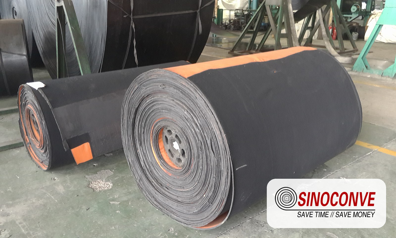
A portable unit set up on sloping ground; levelling and leg stroke matter more than belt tension here.
09Support at Transfer and Elevation Points
Transfers are where a farm line changes direction, changes level, or hands material to another machine, and they crowd more support demand into a few metres than any other part of the run. Here the belt often takes material from a height, the load arrives in surges rather than steady, and the belt may be changing from a troughed shape to a flat one. Each of those puts a demand on the support that the steady-state figure does not capture.
| Point | Support Need | Why It Matters | What to Check |
|---|---|---|---|
| Feed onto a belt | Impact idlers with tighter spacing | Drop energy and surge arrive together | Impact roll condition, skirt clearance |
| Belt to belt in series | Aligned pulleys, transition idlers both ends | Material must land centred on the next belt | Nose-over position, spillage at the joint |
| Elevated discharge | Chute supported independently of the belt frame | The belt must not carry chute weight | Chute fixing, no contact with the belt |
| Trough to flat transition | Three to five transition idler stations | Edge stretch and permanent cupping | Even support, no hard step |
| Change of direction | Self-aligning rollers or a vertical guide | Straightens the belt without fighting it | Roller freedom, guide clearance |
| Crest of a slope | Extra support and hold-down at the crest | Load direction reverses and the belt can lift | Crest rollers, hold-down contact |
Keeping chute loads off the belt frame
Where a chute shares the same frame as the belt, chute loads and belt loads add together, and that is a steady cause of frames that are fine empty and not fine loaded. Keep the chute on its own supports wherever the geometry allows. At a change-of-direction point, a self aligning roller does the straightening job that plain idlers simply cannot, because it corrects the tracking error instead of resisting it.
A truss section at a transfer point; the chute here is carried on its own supports, not on the belt frame.
10Ground Conditions and Foundations
A frame is only as straight as what it stands on. On a farm that surface changes with the season, and the same foundation that holds a line perfectly in August can be a nuisance by February if it was set into ground that moves when it thaws or floods. The rule we use is simple: match the foundation to the ground, and never assume the ground will stay as it was on the day of installation.
| Ground | Foundation Type | Notes |
|---|---|---|
| Concrete pad | Cast-in or resin anchor bolts | Best case for a fixed line; check for voids under the pad |
| Compacted gravel | Precast blocks or ground screws | Common on farms; expect to re-level each season |
| Soft field soil | Timber or steel mud sills, wide pads | Spread the load; count on seasonal settlement |
| Sloped ground | Stepped foundations with uphill hold-down | Never rely on friction alone to hold a leg |
| Seasonally frozen ground | Set depth below the frost line | Frost heave lifts any shallow pad, then drops it unevenly |
| Wet or marshy edges | Piles or screw anchors | Skid foundations will not hold here; rule them out early |
We have seen a line that ran straight all summer develop a persistent left drift every winter, and the cause was one leg on a shallow pad that the frost lifted by a few millimetres and set down again slightly rotated. The bearing and the belt were blamed for two winters before anyone measured the pad. Foundation work is unglamorous, and that is exactly why it gets skipped.
11Maintenance Accessibility and Walkways
The best support system in the world is useless if nobody can reach it. On farm lines, access is usually the first thing traded away, because a walkway costs money and a fence costs nothing to move closer. Three seasons later the line is running on deferred maintenance, and the deferred work is always on the components that needed the most attention.
| Location | Access Requirement | Common Constraint | Practical Fix |
|---|---|---|---|
| Drive end | Walkway about 600 mm wide, removable guard | Tight to a wall or fence | Move the fence, not the guard |
| Return run low points | Reachable to clear caked material | Machine sits low over the ground | Access hatch or raise the machine |
| Idler stations | Tool clearance on at least one side | Pipes or cables crossing the frame | Re-route services above the frame |
| Take-up | Full screw travel visible and readable | Buried under spillage | Containment plus a small platform |
| Loading skirting | Skirt opens without dismantling the chute | Chute blocks the access side | Hinged skirt or bolt-on panels |
| Elevated spans | Guard rail along the access side | No fall protection fitted | Fixed rail plus a fall-arrest anchor point |
Access also drives the spares you keep. A line you can reach is a line you can maintain on a schedule, and a line you maintain on a schedule spends far less on replacement parts. That is why our wholesale conveyor belts range is offered with a matching support-side spares list, so a farm can stock the common faults and not the rare ones.
12Drive and Take-Up Support
The drive end and the take-up carry the highest forces on the whole machine, and their supports are where a farm frame most often shows its limits. A drive puts a torque reaction into the frame. A take-up puts the full running tension into it. If either support is soft, the belt does not fail first; the alignment does, and then the belt fails at the splice.
| Layout | Load Reaction | Adjustment Note |
|---|---|---|
| Foot-mounted head drive | Frame takes the torque reaction | Re-check alignment after any re-tensioning |
| Shaft-mounted gearbox | Torque arm takes the reaction | Torque arm must stay free to move, never locked rigid |
| Screw take-up | Screw and frame take belt tension | Keep roughly 50 mm of travel in reserve |
| Gravity take-up | Frame carries the full tension plus weight | Guide rails straight and clear of build-up |
| Tractor PTO drive | Support sees cyclic load, not steady | Check mount bolts before every use |
On farm machines the drive is often a V-belt pair or set off a tractor, and the support that carries the driven pulley is the part that suffers when those belts are run loose or misaligned. The behaviour of those drives is its own subject, covered by the agricultural V belts guide and the wider rubber V belt guide. As a transmission belt manufacturer we see the support consequence of a slack drive every week, and it is almost always a worn bearing on the driven shaft well before the belt itself is done. The V-belt manufacturer answer is not a stronger belt; it is correct tension and an aligned support.
13Support for Cleated and Sidewall Belts
A cleated or sidewall belt changes the load path through the support, because the raised features have to clear every idler and every transition. On a flat belt the support only holds the carcass. On a cleated belt it also has to let the cleats and walls pass without catching, and the extra belt thickness changes how the belt conforms to the trough. Get that wrong and the belt runs, but it runs until a cleat catches an idler and tears the surface.
| Belt Feature | Support Implication | Design Response | What to Check |
|---|---|---|---|
| Cross cleats | Cleats must clear each idler gap | Make sure cleat pitch does not match idler pitch | Cleat-to-idler contact marks |
| Corrugated sidewalls | Walls ride above the wing rolls | No standard troughing idler where a wall passes | Wall clearance at every station |
| Rigid transverse cleats | Belt cannot trough deeply | Reduce the trough or carry flat | Belt flatness across the carry |
| Return run | Cleats or walls face the rollers | Return rollers must clear them | Return spacing against cleat pitch |
| Skirt and chute | Cleats pass the skirt edge | Wider skirt clearance than a flat belt | Skirt height versus cleat height |
| Take-up and transition | Extra thickness needs more room | More take-up travel; a longer transition | Travel reserve; transition length |
If a farm line is climbing and carrying loose material at the same time, cleats and sidewalls are a common answer, and the support has to be designed around them from the start rather than adapted afterwards. The pattern and wall options are set out in the cleated conveyor belt guide, the load-side selection is covered by cleated conveyor belt bulk handling, and the walled construction is explained in the article on sidewall conveyor belts.
14Inspection Route for Farm Conveyors
An inspection route is worth more than a maintenance schedule, because a route forces the same walk in the same order every time. On a farm line we walk from the feed to the discharge, then back along the return, then under the machine, and we write down what we see. The order matters: walking the same way each time is how you notice a change, and noticing change is the whole point.
| Position | Item | Acceptance Criterion |
|---|---|---|
| Every carry idler | Rotation and shell condition | Turns freely by hand; no flat spot, no wobble |
| Return rollers | Seal and drag | No material packed at the seal; roller turns under light hand pressure |
| Feed zone | Impact rolls and skirt | Impact roll intact; skirt just clears the belt without touching |
| Frame bays | Straightness and bolt torque | No visible bow; witness marks on bolts still aligned |
| Foundations | Footing and level | No lift or rotation since the previous visit |
| Take-up | Travel remaining | At least 50 mm of adjustment left before the limit |
| Belt edges at the support | Edge wear from contact | No fraying or scuff line from a fixed structure |
15Buyer Checklist for Support Systems
When a farm buys a conveyor, the belt gets the attention and the support gets the purchase order. The checklist below is what we would want answered before a support package ships, and it is weighted toward the items that are expensive to change after installation. Anything here that cannot be evidenced is a risk the buyer carries.
| Check Item | Requirement | Evidence | Owner |
|---|---|---|---|
| Design load | Worst-case tonnes per metre, not the average | Load calculation sheet | Line engineer |
| Spacing drawing | Carry, return, frame bay and loading-zone figures shown | General arrangement drawing | Supplier |
| Idler rating | Rating above the worst-case station load, with margin | Rating table | Supplier |
| Environment grade | Outdoor coating, frost and UV rated | Coating and seal specification | Buyer |
| Foundation match | Matched to the actual ground on site | Foundation drawing | Site contractor |
| Access provision | Walkway and removable guard on the access side | Layout drawing | Site |
| Mobile constraints | Stiffness and levelling proven for a portable unit | Undercarriage specification | Supplier |
| Inspection documentation | Criteria and intervals written down | Inspection sheet | Supplier |
16Cost and Service Life of Support Components
Support costs are front-loaded and boring, and that is why they get cut. The honest way to look at them is over the life of the line, not at the purchase order. A sealed return roller costs more per unit than an open one and lasts longer in the open, which usually makes it the cheaper part over a decade even though it looks worse on the invoice. The table gives the ranges we normally see; actual life depends on the site, and we confirm figures against the specific duty before quoting.
| Component | First Cost Basis | Typical Service Life | Replacement Trigger |
|---|---|---|---|
| Standard carry idlers | Per station | 3 to 5 years outdoors | Seized or flattened shell |
| Sealed return rollers | Per station, higher unit cost | 4 to 7 years, longer in dry duty | Seal breach or noticeable drag |
| Impact idlers at the feed | Per station, heavy class | 2 to 4 years at the loading zone | Deformed shell or bearing noise |
| Frame bays | Per metre of run | 10 to 20 years with coating care | Section loss or a permanent bow |
| Foundations | Per leg | 15 years and up if set below the frost line | Heave, settlement, or rotation |
| Walkway and guard | Per meter | 8 to 12 years | Corrosion at the fixings |
| Take-up assembly | Per unit | 5 to 8 years | Travel exhausted or screws worn |
Two habits pay for themselves on farm lines. Keep a small spares stock of the components that fail most, and buy the whole support package, belt included, in one enquiry so the drawings and the hardware agree. A single consolidated order through our conveyor belt catalog and support list is cheaper to administer than three orders from three suppliers who each assumed the others had covered the frame.

17Frequently Asked Questions
How far apart should farm conveyor idlers be?
It depends on the load, and on little else to first order. For grain and produce up to about 0.6 t/m, set carry idlers 1.2 to 1.5 m apart and frame bays 2.0 to 3.0 m; below 0.3 t/m you can stretch the carry spacing toward 1.8 m. Halve the loading-zone spacing near any feed. If someone quotes you a single number without first asking the load, that number is a guess.
What load can a farm conveyor support take?
The support takes whatever the belt puts on it, so the useful question is about the station. Take the distributed load in tonnes per metre, multiply by the spacing, and you have the static load per idler. Then add the impact and wet-season allowances. On the heavy farm duties we survey, a station designed for 300 kg is common even where the average static load is under 50 kg.
Which frame spacing suits a portable unit?
Short ones, and shorter than the fixed-line table suggests. A portable frame is limited by stiffness under wind and uneven ground rather than by material load, so we cut the bay to roughly 2.0 to 2.4 m and tighten from there. Reduce the span before you reach for more belt tension; tension will only hide the flex until the machine sits on a slope.
How does dust affect support components?
It seizes them. Grain and chaff dust takes on moisture, sets almost like mortar around a bearing seal, and stops the roller turning. Use sealed rollers on any dusty line, fit a plough scraper ahead of the tail, and clear the return run weekly in season. Those three habits removed almost all of the roller seizures on the open lines we look after.
What changes for an open-air line?
Everything that was optional indoors becomes required outdoors: UV-stabilised covers, galvanised or epoxy frames, sealed bearings, drainage in every trough, and a low-temperature belt grade if the site freezes. Frost and wind are the fast threats; corrosion and sun are the slow ones. Inspect at the first frost, not after it.
How do I support a line at an elevation change?
Put the chute on its own supports, never on the belt frame, and add support at the crest and the foot of the slope. At the crest the load direction reverses and the belt can lift, so a hold-down is often needed. If the change also moves from a troughed section to a flat one, allow three to five transition idler stations so the belt edges are not stretched.
What ground conditions break a farm conveyor frame?
Moving ground, not heavy load. A shallow pad in seasonally frozen soil can heave and settle back rotated, and one lifted leg will hold a drift all winter. Soft field soil needs mud sills or wide pads, marshy edges need piles or screw anchors, and sloped ground needs a stepped foundation with an uphill hold-down. Friction alone will not hold a leg on a slope.
How much access space does maintenance need?
About 600 mm of walkway at the drive end is the figure we design to, with a guard that comes off without dismantling the machine. Elsewhere you need tool clearance on at least one side of each idler station and full, readable screw travel at the take-up. If a fence or a cable tray blocks that, move the fence or re-route the tray. Access is paid for once; the lack of it is paid for every season.
Do cleated belts need different support?
Yes, and the difference is clearance rather than load. Cleats must pass each idler gap without contact, and corrugated sidewalls ride above the wing rolls, so a standard troughing idler cannot sit where a wall passes. Check that the cleat pitch does not match the idler pitch, and give the return run the same inspection. A cleat that catches an idler tears the belt surface in a single pass.
Where should I place the take-up on a farm conveyor?
At the tail on most farm lines, so the slack side takes the adjustment and the drive end stays fixed and aligned. Screw take-up suits short and portable machines where a person checks it weekly; gravity take-up suits long fixed lines where the tension has to look after itself. Whichever you choose, keep about 50 mm of travel in reserve. Run out of travel and the belt is finished even if the rubber is perfect.
How do I inspect support components seasonally?
Walk the same route in the same order, from the feed to the discharge and back along the return. Check every carry idler for free rotation and flat spots, the return rollers for seal condition, the frame bays for a bow, the foundations for any lift, and the take-up for remaining travel. Write it down. The value is in comparing this visit with the last one, not in the visit itself.
What is the service life of farm support parts?
Outdoors, plan on three to five years for standard carry idlers, four to seven for sealed return rollers, and two to four for impact idlers at a busy feed. Frames last ten to twenty years with coating care, and foundations fifteen and up if they sit below the frost line. Those are the ranges we normally see; actual life is set by the site, so confirm the figures against your own duty.
18Related Products You May Need
- Conveyor rollers and idler sets for the carry, return and impact stations this page spaces out.
- Chevron and patterned belts for farm lines that climb and must hold the load.
- Rubber conveyor belts for grain, produce and general farm bulk.
- V-belts for farm drives where the support carries a driven pulley.
- Full product catalog to place belt and support hardware in one enquiry.
19Related Blog Posts
- Agricultural V-belts for reliable farm power for the drive that loads the support at the head end.
- Cleated conveyor belts for inclined crop handling when the line has to climb.
- Farm chevron conveyor belt efficiency on the patterned option for slopes.
- Conveyor idler and roller guide for roll geometry, bearings and seals.
- Steel conveyor rollers selection guide for matching roll class to bay load.
- Self-aligning roller selection for transfer and change-of-direction points.