
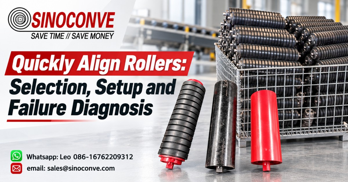
Quickly Align Rollers: Selection, Setup and Failure Diagnosis
To quickly align rollers safely, lock out the conveyor first. Verify that the structure is square and clean, mark the belt edge at fixed measurement stations, and identify whether drift is local, progressive, or linked to the splice. Adjust only the affected idler or pulley in small increments. Then run several complete belt revolutions unloaded, repeat the observation under a controlled load, and record every change. Never randomly knock rollers or over-steer an idler. That practice hides the real cause, creates a second tracking error, and puts hands near stored energy without producing a repeatable result.
This is our field sequence for an urgent tracking correction after a shutdown, not a guide to choosing a self-aligning roller. We focus on references, cause isolation, controlled adjustment, restart observation, and failure diagnosis. When the hardware itself needs replacement, our conveyor roller range is the correct starting point for an RFQ. When the question is roller type or duty selection, use our separate idler roller selection guide.

01Define the Tracking Problem Before Touching a Roller
Maintenance crews lose valuable shutdown time when the first observation is reduced to “the belt runs left.” Left where? Under which load? At what speed? Does the edge return after the splice passes? A useful diagnosis starts with location, timing, and direction. We establish four to eight numbered stations along the carrying run and return run, depending on conveyor length. A chalk mark on the structure and a measured edge position give the crew a common reference. Without that reference, one technician sees improvement while another sees a new fault thirty meters downstream.
Classify the drift into one of three patterns
A one-location drift appears near one idler set, a loading zone, a transition, or a contaminated pulley. The belt may be centered before that station and displaced immediately afterward. Progressive drift builds gradually through several frames; this usually directs our attention toward cumulative idler skew, structure alignment, tension inequality, or a pulley reference. Once-per-revolution drift follows one part of the belt. Mark the belt and watch. If the same marked zone moves sideways each circuit, inspect the splice, local carcass damage, or a permanent camber instead of chasing rollers around the conveyor.
Separate a symptom from its point of origin
The point where an edge first becomes visible near a guard is not always the origin. Belt steering develops over distance. We work upstream from the visible displacement, station by station, while respecting the direction of travel. A badly centered loading stream can begin a lateral force at the chute, yet the edge may not approach the frame until the next three troughing sets. For broader belt behavior and carcass effects, our EP conveyor belt tracking guide provides useful supporting context.
| Observed pattern | Fast field clue | First area to inspect | Do not assume |
|---|---|---|---|
| Local at one station | Centered entry, displaced exit | That frame, roll rotation, buildup, nearby loading | A training idler will cure contamination |
| Progressive over several bays | Edge offset grows at successive marks | String line, pulley axes, cumulative frame skew | The last roller is the cause |
| Once per belt revolution | Offset follows a marked belt section | Splice geometry, carcass damage, camber | Every idler needs steering |
| Changes with loading | Empty belt centers, loaded belt walks | Feed position, skirt drag, trough support | Unloaded acceptance is enough |
02Make the Conveyor Safe and Stable
Tracking work is not a reason to bypass lockout. Rotating belts, gravity take-ups, stored tension, and rolling components can move without warning. We isolate electrical, hydraulic, pneumatic, and gravitational energy under the site procedure. The crew verifies zero energy, secures take-up movement where required, and confirms who controls each lock. Guards are removed only under authorization and refitted before a powered test. Observations during operation must be made from protected positions; adjustment happens after the conveyor is stopped and isolated again.
Stop alignment when the condition exceeds a field correction
A torn edge, exposed carcass, hot bearing, displaced pulley, cracked frame, failed take-up, or material trapped between belt and pulley is not a “quick tweak.” Stop. Escalate it. The same applies when the belt is close enough to a fixed structure to cut the cover during a test run. Correcting roller angle while a structural member is bent simply forces the belt to tolerate a defect. That is neither safe nor durable.
Stabilize process conditions before comparing readings
Record belt speed, approximate feed rate, material moisture, recent washdown, and ambient conditions. A rain-soaked limestone feed can load a belt differently from dry product. At a transfer point, a 20% feed-rate change may shift the stream enough to produce a new lateral force. We do not claim that one centered empty pass proves success. We compare like with like and state what changed. This discipline matters whether the belt came from a local source or a global conveyor belt manufacturer.
Field note from our engineers: At one aggregate transfer, the empty belt looked acceptable for two circuits. Under normal stone flow, it moved 18 mm toward the walkway within five stations. The roller settings were not the first fault. A worn chute liner had moved the stream off center. After the flow was centered, only one modest idler correction remained necessary.
03Choose Between Ten-Minute Triage and a Full Survey
An urgent stoppage does not always allow a full geometric survey, but urgency must not become guesswork. Our ten-minute triage checks for obvious and high-consequence faults: accumulated carryback, a seized or missing roll, gross frame movement, off-center loading, a visibly skewed pulley, a fresh splice, and a take-up at its travel limit. If one cause is clear, correct it, establish reference marks, and test. If evidence conflicts or several stations drift progressively, move to the full survey rather than stacking compensating adjustments.
The ten-minute diagnostic route
Walk the accessible conveyor from discharge toward loading while it is locked out. Look at belt-polish patterns on rolls, compare edge clearance, hand-check free rotation where safe, and inspect the return path for carryback lumps. Use a noncontact temperature instrument only as a screening tool; a warmer bearing may indicate drag, but emissivity, sunlight, and residue affect readings. Mark any suspect station. The team leader selects one likely cause rather than issuing simultaneous adjustments across the line.
When a full survey is mandatory
Use a full survey after structural work, pulley replacement, a major splice, collision, repeated tracking failures, or any progressive error that returns after cleaning. It is also justified when previous crews have left many idlers visibly skewed in opposite directions. The survey establishes centerline, elevation where relevant, frame squareness, pulley-axis relationships, and belt position. Our separate roller types and load ratings reference helps identify installed components, but this procedure stays focused on geometry and correction.
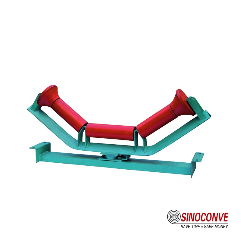
Fixed stations turn a vague tracking complaint into comparable edge-position data.
04Build a Baseline with Simple Tools
A practical kit includes a tensioned string or suitable laser, machinist’s or framing square, steel tape, chalk, straightedge, feeler gauges where appropriate, spirit level, inspection light, and an infrared temperature instrument. Add tags or a notebook for the station log. The laser is not automatically superior: dust, vibration, sunlight, and an unstable mounting point can create false confidence. A well-set string referenced to known frame points often gives clearer field evidence.
Create fixed stations and measure from one datum
Number each station and choose a repeatable structural datum, not a bent guard or skirt rubber. Measure both sides where possible. Record frame width, belt-edge clearance, roll-end positions, and the direction of travel. Do not switch from the left stringer at one station to the right stringer at another without documenting the change. On wide, long conveyors, temperature and structure movement can affect dimensions, so the survey should note whether the line was cold, warmed by operation, or exposed to direct sun.
Check rotation, surface condition, and temperature
Every roll in the suspect zone should rotate freely and present a usable surface. A bearing can turn by hand yet drag under belt load, while a packed shell can change effective diameter. Compare neighboring rolls, listen during a guarded run, and inspect contact polish. For dusty service, the practices in our fine-dust sealed roller article help explain why contamination control matters. Replacement details should be taken from the existing roll and frame, not guessed from appearance.
| Tool or check | What it establishes | Common field error |
|---|---|---|
| String or laser | A repeatable conveyor centerline and accumulated skew | Referencing a deformed stringer without checking it |
| Square and straightedge | Local frame and idler relationship | Squaring to a loose bracket |
| Tape and chalk | Edge offset at fixed stations and a belt revolution mark | Moving the station between test runs |
| Temperature screening | A comparative clue for bearing drag | Treating one infrared reading as a bearing diagnosis |
| Rotation check | Freedom of movement and roughness | Testing while stored energy is uncontrolled |
05Understand the Steering Law and Its Limits
A moving belt tends to travel toward the end of a roller or idler that it contacts first. Technicians often summarize this as “the belt moves toward the leading end.” That is a useful steering law, but only after direction of travel and actual belt contact are confirmed. If an idler is slightly skewed, one end meets the belt earlier and creates a lateral steering influence. We mark the original position, identify the leading end, and make a small controlled change. Then we watch enough complete revolutions for the effect to reach downstream stations.
Why the rule can mislead a hurried crew
The law does not override physics elsewhere. A wet layer on one pulley face, a crowned buildup, eccentric loading, a crooked splice, or unequal tension may dominate the weak steering effect of one idler. A belt that barely contacts a wing roll will not respond like one seated evenly in a trough. Reversible service flips the leading-end relationship when direction changes. Finally, steering a roller to force an already damaged belt away from a frame can increase edge stress rather than solve the defect.
Use contact evidence before choosing adjustment direction
Inspect polish, dust wiping, and material marks on the roller shell. Look for a gap under one side of an unloaded belt or an uneven contact band after operation. The desired adjustment is based on the actual roller face seen by the traveling belt. We draw a travel arrow beside every adjusted frame because verbal directions such as “push the left side” become ambiguous when the observer changes position. This small habit prevents reversal errors during a multi-person shutdown.
Tracking response also depends on belt construction and condition. A suitable conveyor belt supplier should provide construction data that helps the maintenance team interpret stiffness and trough behavior; it cannot make structural misalignment disappear.
06Adjust One Variable in Controlled Increments
There is no universal adjustment such as “move every idler 5 mm.” Frame spacing, belt width, tension, speed, trough angle, material load, and available slot length all change the response. Our procedure uses the smallest practical movement that can be marked and measured on that conveyor. On a compact frame, that may be a barely visible angular change. A large overland structure may require a different physical displacement to create the same small angle. The control principle, not a magic millimeter figure, is transferable.
Mark, loosen, move, secure, and measure
Scribe or chalk the original bracket position. Confirm which fasteners locate the frame and which provide clamping force. Support heavy components by the approved method. Move one end only when that is the intended adjustment, tighten to the site or equipment requirement, and measure the new position before restart. A loose fastener can allow the idler to wander under load, making a temporary improvement look like an unexplained recurrence.
Allow the conveyor to show the complete result
After restart, observe several full belt revolutions, not merely ten seconds of movement. A long conveyor needs time for the altered belt path to reach the next stations. Mark the splice or another known belt point and count complete circuits. If the belt continues to improve slowly, do not add a second adjustment before the response stabilizes. If it moves rapidly toward danger, stop immediately. Return to the prior mark and reassess the direction or root cause.
| Step | Controlled action | Observation gate | Stop condition |
|---|---|---|---|
| 1. Baseline | Record edge position at every fixed station | Pattern is repeatable for complete circuits | Belt approaches fixed structure |
| 2. Isolate | Select one causal frame or pulley issue | Evidence agrees with travel direction | Cause remains uncertain |
| 3. Mark | Preserve original fastener and bracket positions | A rollback reference is visible | Mount is damaged or loose |
| 4. Adjust | Make one small, measurable angular change | Fasteners are secured before testing | Slot travel or frame condition is inadequate |
| 5. Run empty | Observe several full revolutions from safe points | Response stabilizes and is logged | Rapid adverse movement or abnormal sound |
| 6. Run loaded | Increase to a documented normal condition | Clearance remains acceptable at all stations | Load changes direction or edge risk |
Field note from our engineers: We once reviewed a return run where three consecutive frames had been skewed during separate shifts. Each adjustment briefly improved the nearest observation point, but the combined angles sent the belt back across the structure farther downstream. Returning all three frames to measured square, cleaning one return roll, and then making a single marked correction produced a stable path.
07Treat Carrying and Return Runs Differently
The carrying run is influenced by trough geometry and the material stream. The return run is usually flatter, more exposed to carryback, and often has different roller spacing. A correction on one side can affect entry into a pulley and therefore influence the other side. We label every recorded point as carry or return; otherwise the maintenance log becomes difficult to interpret. A return roller should not be skewed just because the visible problem appears above it.
Carrying-side corrections begin with loading
Watch where material lands relative to the belt centerline. Check skirt pressure and whether one side traps fines. Inspect impact support for a collapsed component or uneven bed. The loading-zone impact roller guide explains that environment without turning this article into a purchasing comparison. If the stream lands off center, correct chute geometry or flow before using idler skew as compensation. A centered empty belt can still track poorly once asymmetric load enters.
Return-side corrections begin with cleanliness
Carryback adheres to the dirty side and transfers to return rolls. Uneven buildup changes the shell diameter and creates an unintended crown or taper. Clean the roller and belt before measuring alignment. Review the belt cleaning methods and schedules if residue returns quickly. Cleaning does not replace geometric checks, but geometry measured over a 6 mm lump of compacted fines is not meaningful.
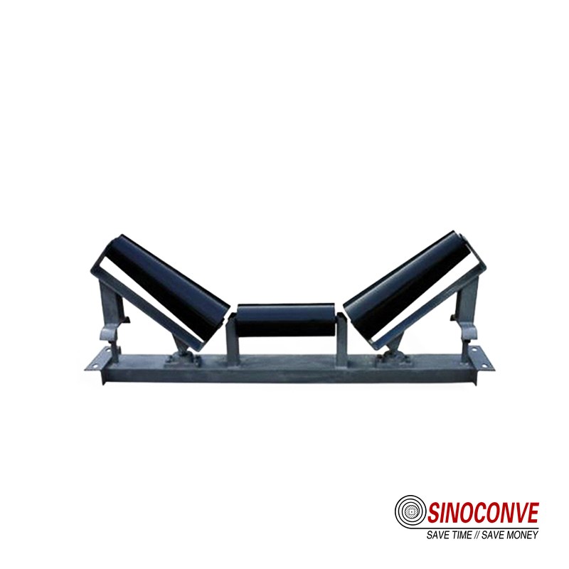
08Diagnose Root Causes Instead of Over-Steering
Alignment rollers can influence belt position, but they cannot straighten a twisted structure, repair a splice, free a seized bearing, or center a loading stream. When many rollers require aggressive opposing angles, assume the system is being forced around a primary defect. We restore neutral geometry and find that defect. This protects the belt edge and reduces drag, which matters on every heavy industrial conveyor belt installation.
Off-center loading and skirt drag
An off-center stream introduces lateral momentum and unequal burden. Skirt rubber pressed harder on one side adds friction. Evidence includes an empty belt that tracks normally, a loaded belt that walks consistently, asymmetrical material depth, and one polished skirt. Correct the feed trajectory, chute liner condition, and skirt setting. Do not angle six downstream idlers to fight the stream; a future feed change may then send the belt sharply the other way.
Buildup and seized idlers
Buildup alters effective diameter. A seized center or wing roll changes drag and support, sometimes pulling the belt toward one side and sometimes disturbing the trough enough to create a delayed response. Replace a failed roller rather than asking adjacent frames to compensate. SINOCONVE manufactures rollers and belts in Ningbo, China, with product information available through the conveyor roller product hub. For a replacement RFQ, measurements and duty data remain essential.
Skewed pulleys and uneven tension
A pulley-axis error influences a large wrap area and can dominate idler corrections. Check shaft references, bearing housing positions, lagging condition, and buildup. Uneven take-up movement or a jammed carriage can produce unequal tension. Never reposition a pulley casually; pulley alignment affects wrap, take-up travel, and downstream geometry. If the survey shows a structural or take-up problem, involve the responsible mechanical engineer before restart.
Frame twist and settlement
A square laid on one local bracket cannot reveal a long structure that has settled. Compare centerline and cross measurements across multiple bays. Look for changed support elevations, cracked welds, loose anchors, or impact damage. On mobile or temporary conveyors, ground conditions matter. Restore structural references before fine tracking. A conveyor belt factory can supply suitable products, but site steelwork controls the installed alignment datum.
| Root cause | Typical evidence | Corrective priority | Why roller steering alone fails |
|---|---|---|---|
| Off-center loading | Loaded drift; uneven burden depth | Center the stream and inspect liners | Lateral input remains at every load cycle |
| Buildup | Uneven shell diameter; repeating residue | Clean and correct cleaner performance | The contact geometry changes again |
| Seized idler | Heat, noise, flat spot, abnormal polish | Replace and verify adjacent mounts | Drag and support remain unequal |
| Skewed pulley | Broad tracking influence near pulley | Survey shaft and bearing references | Large wrap contact dominates small idler inputs |
| Crooked splice | Deviation follows splice each circuit | Measure and repair the splice | One fixed roller cannot follow a moving defect |
| Uneven tension | Take-up binding or unequal edge behavior | Restore take-up function and references | The belt enters support with unequal forces |
| Frame twist | Progressive error and inconsistent cross levels | Repair structure and foundations | Each roller inherits a faulty datum |
09Recognize Splice-Linked and Belt-Linked Drift
Mark the belt at the splice and at one additional reference point. During a protected run, record edge offset as those marks pass selected stations. If lateral displacement arrives with the same belt section each revolution, stop changing fixed rollers. Measure splice straightness relative to the belt centerline, inspect cover and carcass condition, and look for local stiffness or thickness differences. A tracking frame stays in one place; the defect travels. Steering the entire conveyor around that traveling defect can damage an otherwise acceptable belt path.
Confirm the period instead of trusting memory
Use a stopwatch only as a secondary aid. The physical mark is stronger evidence because belt speed may vary. Note whether the offset peaks at the splice itself, ahead of it, or across a longer repaired section. Repeat at least several circuits. If the peak appears at different belt locations, the issue may be changing load or residue rather than splice geometry. Record observations in plain language with station numbers; video from a protected location can support the log where site rules permit it.
Decide whether operation can continue
A minor periodic movement within documented clearance may be monitored while a repair is planned. Edge contact, exposed fabric, opening splice steps, abnormal vibration, or rapidly growing displacement requires a stop. The decision belongs within the site risk procedure. For belt replacement or splice support, buyers can consult a qualified rubber conveyor belt source and provide measured construction, width, cover, duty, and existing splice information.
10Verify Reversible Conveyors in Both Directions
A setting that centers a belt in one direction may push it off line in reverse. The leading end of a skewed idler changes when belt travel reverses, and loading geometry may also change. Therefore, a reversible conveyor is not accepted after a single-direction test. We establish separate station records for Direction A and Direction B, mark the arrows on the structure, and test representative unloaded and loaded conditions in each permitted direction.
Favor true squareness over heavy directional steering
Reversible lines usually tolerate less deliberate idler skew. Begin with frames square to the surveyed centerline, clean contact surfaces, correct pulley references, and centered feed in both modes. Small residual corrections must be judged by their bidirectional effect. If one direction requires a strong compensating angle, find the directional root cause: a diverter position, one-sided chute wear, asymmetric cleaner contact, or a take-up response that differs during reversal.
Use a four-condition acceptance test
At minimum, record empty Direction A, loaded Direction A, empty Direction B, and loaded Direction B. “Loaded” should state approximate feed or a repeatable production condition rather than simply saying normal. Observe startup, steady travel, and stopping behavior if these are part of the operating concern. A belt can shift during acceleration and settle later; that transient still matters when edge clearance is tight.
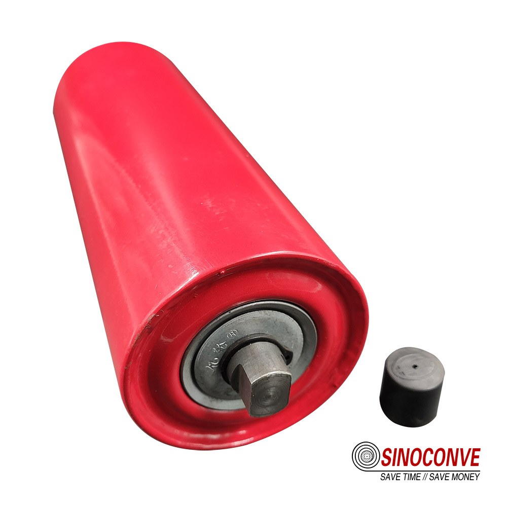
11Know When Alignment Rollers Are the Wrong Fix
An alignment roller is the wrong fix when the dominant fault is off-center loading, heavy carryback, a seized roll, pulley skew, splice error, uneven tension, frame twist, or belt damage. It is also wrong when the crew needs extreme steering angles to keep the edge clear. Self-aligning components can be useful within a sound system, but this article deliberately does not select them. For that separate question, read our self-aligning roller selection article.
Signs that compensation has replaced correction
Look for alternating idler angles, adjustment slots at their limits, bright edge wear, high drag, and a belt path that changes after cleaning. Another sign is a conveyor that tracks acceptably only at one narrow feed rate. These conditions tell us the system has accumulated compensations. We photograph and mark each frame, return suspect frames to a surveyed neutral position in a planned sequence, and re-diagnose the primary inputs. Doing this all at once without a plan can create a severe short-term tracking risk.
Escalate design and structural issues
Inadequate transition distance, poor chute geometry, insufficient edge clearance, a weak frame, or incompatible pulley arrangement requires engineering review. A roller catalog cannot solve those conditions. When general roller selection data is needed after the geometry is corrected, use the conveyor roller selection guide. For general system sourcing, a conveyor belt distributor may coordinate components, yet final dimensions must come from verified drawings and field measurements.
12Restart, Observe, and Define Acceptance
The restart plan assigns one person to authorize movement, observers to protected stations, and a clear stop signal. Guards and temporary tools are accounted for. Begin under the lowest safe controlled condition allowed by the site procedure. Watch belt entry and exit at the adjusted station, then downstream response. Several complete revolutions are necessary because the belt and splice must pass repeatedly. Record edge offsets rather than relying on “looks better.”
Use unloaded operation as a gate, not final proof
An unloaded run verifies gross direction, abnormal noise, free rotation, and immediate clearance. It does not reproduce material momentum, skirt contact, loaded sag, or the real trough shape. Once the empty path is stable, introduce a controlled load and watch the same marked stations. Increase toward a documented production condition only if clearance remains safe. If loaded drift appears, return to loading, support, and tension diagnosis instead of automatically increasing idler angle.
Set measurable acceptance limits for the actual conveyor
We do not publish one universal acceptable edge offset. Available clearance, belt width, speed, splice condition, structure, and site standards differ. The owner should define minimum edge clearance and maximum stable offset for the installation. Acceptance includes no frame contact, no abnormal roller heat or noise, secure fasteners, repeatable position over the agreed number of revolutions, and stable behavior at the agreed load. Reversible equipment must pass in both directions.
| Acceptance item | Record | Evidence of completion |
|---|---|---|
| Edge clearance | Measured offset at every numbered station | Within the site-defined limit for repeated circuits |
| Test condition | Direction, speed, approximate feed, moisture | Representative operating state documented |
| Adjustment | Frame number, end moved, measured amount, time | Original and final marks remain traceable |
| Mechanical condition | Rotation, sound, temperature comparison, fasteners | No abnormal change after loaded test |
| Follow-up | Inspection owner and operating-hours checkpoint | Named responsibility, not an open note |
13Prepare a Useful Replacement Roller RFQ
If inspection finds a seized, worn, bent, or contaminated roller, the RFQ should make the replacement identifiable. Send roller position, face length, overall shaft length, shaft-end geometry, diameter, bearing arrangement if known, seal environment, frame slot details, belt width, trough angle, speed, duty, material, temperature, and photos with a scale. State whether the roll is carry, return, impact, or another existing position. Do not request “the same standard roller” without dimensions; site modifications and regional conventions make that phrase risky.
Distinguish verified dimensions from estimates
Tag each dimension as measured, taken from a drawing, or estimated. A worn shell diameter should not silently become the specified new diameter. Photograph shaft ends straight-on and from the side. Include mounting centers and available clearances. If a drawing conflicts with the installed component, show both and explain which one the replacement must fit. Our team can review data, but manufacturing confirmation depends on actual duty and drawings.
Connect the roller request to belt duty
Provide belt width, construction, speed, material lump size, bulk density if known, loading condition, hours, water exposure, dust, and corrosion. This is more useful than a generic request for heavy duty. Ningbo Sinoconve Belt Co., Ltd. manufactures conveyor and transmission belts and has in-house vulcanizing, forming, inspection, and splicing service capabilities. Buyers seeking wholesale conveyor belts can use the catalog, while roller requests should still include the field details above.
Drive-system inquiries belong in a different scope. A transmission belt manufacturer or V-belt manufacturer addresses power transmission, not conveyor tracking idlers. Keeping those RFQs separate reduces drawing errors.
| RFQ field | Minimum useful detail | Why it matters |
|---|---|---|
| Installed position | Carry, return, impact, station number | Connects dimensions to actual loading |
| Roll geometry | Shell diameter, face, shaft, end details | Controls physical fit and contact |
| Mounting | Slot, center distance, bracket photos | Avoids shaft-end mismatch |
| Duty | Belt width and speed, load, material, hours | Supports bearing and shell review |
| Environment | Dust, water, temperature, corrosion | Guides sealing and material discussion |
| Evidence | Drawing revision and scaled photographs | Makes assumptions visible before production |
14Use a Shift-Ready Fast Alignment Checklist
Under shutdown pressure, a compact sequence helps the crew avoid repeating old mistakes. First, lock out and control every energy source. Second, clean the suspect zone and identify fixed stations. Third, classify drift as local, progressive, load-related, or once-per-revolution. Fourth, inspect rotation, buildup, loading, structure, pulleys, splice, and take-up. Fifth, select one cause. Sixth, mark one small correction. Seventh, test for several full revolutions empty and under a controlled load. Eighth, document readings, fastener status, and follow-up responsibility.
What the team leader should ask before restart
Has every tool been removed? Are all required guards installed? Is the original adjustment mark visible? Which observer owns each station? What signal stops the test? How many complete belt circuits will be watched? At what feed condition will loaded acceptance occur? Has the team agreed on a site-specific edge-clearance limit? These questions take less time than recovering from an uncontrolled second adjustment.
What to preserve for the next shift
Leave a concise record with date, time, conveyor ID, travel direction, station readings, belt revolution mark, observed pattern, root cause, adjustment, test load, and remaining risk. Attach photographs that show the datum and final bracket position. Do not write only “aligned rollers.” A later shift needs to know whether the belt was proven loaded, whether a splice-linked movement remains, and whether a replacement roller has been requested.
Fast alignment is disciplined diagnosis compressed into a safe sequence. It is not random impact with a hammer, and it is not a substitute for cleaning or structural repair. Our engineers use measured stations and one-variable changes because those practices make the result repeatable. They also make procurement clearer: a replacement can be specified from evidence instead of from the failed component’s color or an uncertain catalog nickname.

15Frequently Asked Questions
Which way should I move an idler to steer the belt?
The belt generally moves toward the end of the roller it contacts first, often called the leading end. Confirm the actual direction of belt travel and contact before acting. Mark the original position, make a small angular change, secure the frame, and observe several complete revolutions. Reverse the logic carefully on a reversible conveyor.
Can we align rollers while the conveyor is running?
No hands-on adjustment should occur around a moving belt. Observe only from protected positions under the site procedure, then stop, isolate, lock out, and verify zero energy before changing a component.
How far should we move a roller?
There is no universal millimeter value. Use the smallest practical, measurable increment for the frame and conveyor, because angle and response depend on width, spacing, tension, speed, load, and structure. A marked tiny correction followed by a complete test is safer than a large unrecorded movement.
Why does the belt track correctly empty but drift when loaded?
Start at the feed. An off-center stream, unequal skirt pressure, impact-support damage, loaded sag, or tension behavior can appear only under material. Do not accept the empty run as final proof, and do not immediately increase roller skew.
Why does the tracking error return once every belt revolution?
That rhythm points toward a belt-linked cause. Mark the splice and another belt point, then confirm whether the lateral movement follows the same section for several circuits. Inspect splice straightness, localized repair stiffness, carcass damage, and camber. Fixed rollers are unlikely to be the primary cure for a defect that travels.
Should several idlers be adjusted together to save shutdown time?
No. How would the crew know which change helped? Adjust one causal variable, log it, and allow the response to stabilize. Multiple simultaneous changes destroy the diagnostic trail and can create a delayed downstream overcorrection.
Will a self-aligning roller solve persistent mistracking?
Not when the root cause is loading, buildup, a seized idler, pulley skew, splice geometry, unequal tension, or frame twist. Correct those faults first. Selection of self-aligning hardware is covered in the linked product-selection article, not in this field procedure.
How many belt revolutions should we observe?
Enough complete circuits to show that the response is repeatable and that the splice has passed each critical station several times. Conveyor length and speed change the required time, so a single universal count is not defensible. Record the actual number and the condition under which acceptance was made.
What changes on a reversible conveyor?
The leading-end relationship reverses, and the feed arrangement may create different forces in each direction. Begin from accurate squareness and avoid heavy directional steering. Test empty and loaded in both directions before acceptance.
When should the conveyor remain stopped?
Keep it stopped for frame contact, a torn edge, exposed carcass, a hot or seized bearing, unstable pulley or take-up, cracked structure, trapped material, opening splice damage, or any condition outside the site’s defined safe limit. Escalate instead of steering around the hazard.
16Related Products You May Need
- Conveyor rollers for measured replacement requests across carry and return positions.
- Rubber conveyor belts for mining, quarrying, cement, port, and general bulk handling duties.
- EP fabric conveyor belts with construction options reviewed against actual duty and drawings.
- Heat-resistant conveyor belts for elevated-temperature material handling after operating data are confirmed.
17Related Blog Posts
- Conveyor Idler Roller Guide: How to Choose the Right One
- Self-Aligning Roller: Choosing the Right Conveyor Solution
- Conveyor Roller Selection Guide for Reliable Material Handling
- EP Conveyor Belt Tracking Guide
- Conveyor Roller Ultimate Guide 2026: Types, Materials and Load Ratings
- Conveyor Belt Cleaning Methods, Schedules, and When Scrapers Will Not Work