
Port Conveyor Belts: Steep Transfer, Spillage Control and Bulk Terminal Selection (2026)
At a bulk terminal, a port conveyor belt earns its keep by not stopping the ship. Berth time is the most expensive clock on the site. Demurrage runs whether the stacker is reclaiming or the belt is sitting under a chute with a torn edge, and the maintenance window usually opens only after the vessel has sailed. That single fact explains why port conveyors are specified differently from quarry or plant conveyors, even when the tonnage looks similar on paper. Short centers with a big lift, four to six starts an hour under full load, salt in the air twelve months a year, and a transfer point that is expected to run clean in a 25 km/h crosswind.
SINOCONVE has been building belting out of Ningbo since 1988, and a fair share of what leaves our presses goes into port and stockyard duty: EP and steel cord carcasses, chevron profiles, corrugated sidewall and cleat assemblies, plus the V-belts and rollers around the drives. Our view of port work is deliberately narrow. We do not sell unloaders, shiploaders or stacker-reclaimer booms. We supply the belt that sits inside them, and we have to answer for it when a lift segment starts slipping or a transfer tower starts raining coal onto the jetty. As a conveyor belt manufacturer working with terminal contractors and package EPCs, most of our port conversations start with a drawing and a complaint rather than a part number.
This guide is written for the people who have to sign the specification: terminal engineers, mechanical package managers, and maintenance planners. It sets out four duty classes you will find at almost any dry bulk terminal, a decision table that maps each class to a belt type and carcass, an angle-to-profile matrix, a countermeasure list for spillage and carryback, notes for salt-laden and high-humidity sites, the splice requirements that come with a lift section, and a full capability and incline calculation you can follow with your own numbers. Nothing here replaces the terminal's own design standard, but it should shorten the argument about which belt goes where.

01What Port Duty Does to a Belt That Works Fine in a Quarry
A quarry conveyor usually runs a long, gentle, mostly horizontal route with a steady feed from a crusher. A port conveyor is the opposite animal. The route is short because land at the quay is scarce, so the designer has to gain elevation quickly. On a ship unloader or a shiploader boom, the belt is inside a moving structure that telescopes, slews and luffs. On a stacker-reclaimer, the belt runs on a boom whose incline changes with the pile height. The belt has no choice about any of this. It simply has to work.
A duty cycle that punishes the carcass
Start counting starts. A terminal that runs three shifts and staggers its shiploader between holds may start the same lift belt twenty to thirty times a day, and each start puts a tension spike through the carcass and the splice. Steady-state tension is not the design case. The design case is the worst start of the week, when the boom is fully loaded, the take-up is at the end of its travel, and the operator gets impatient. We ask for the number of starts per hour and the drive arrangement before we size anything, because a direct-on-line motor and a variable-frequency drive put very different peaks through the same belt.
Then add the geometry. Short centers mean short transition distances from the troughing idlers to the pulleys, which concentrates edge stress. High lift means a heavier tension on the high side and a longer take-up travel to absorb elastic stretch. If the take-up has already used most of its stroke, a belt change becomes a structural problem rather than a wear problem.
The three failures we see most on the quay side
First is edge damage at the transfer point. The chute is rarely centered on the belt, the material arrives with a horizontal velocity, and the belt edge becomes a grinding surface. You can see the result as a frayed skirt line along one side, usually the same side every time. Second is carryback feeding a slow misalignment. Fines stick to the return strand, build up on the return idlers, and push the belt off-center until a tracking frame can no longer correct it. Third is rubber loss in the cover, not from abrasion alone but from a combination of abrasion, moisture and time. A cover that looks adequate at handover can be down to the breaker ply after a few wet seasons if the compound was chosen for price.
Why meters are the wrong unit of cost
Port procurement is often forced into a per-meter comparison, and that comparison quietly assumes the belt is a consumable like a filter. On a lift section it is not. A belt that lets the load slip back at 30 degrees forces the operator to reduce feed, which reduces the ship's discharge rate, which is the number the terminal is actually paid on. Working from our port bulk material handling experience, we usually argue the case in tonnes per hour retained rather than dollars per meter saved. It is a harder conversation to win, but it is the honest one.
02Four Duty Classes at a Bulk Terminal: A Selection Decision Table
Most port conveyors fall into one of four families. Classify the duty first, then choose the belt. Doing it in the other order is how terminals end up with a smooth EP belt on a 32-degree boom and a heavy chevron on a flat yard conveyor where it traps material and wears the skirt rubber.
The four classes in one table
| Duty class | Typical incline | Belt type we would quote first | Carcass | Main risk |
|---|---|---|---|---|
| 1. Stockyard to quay, long haul, fixed route | 0 to 16 degrees | Smooth cover, abrasion-resistant | EP fabric, 3 to 5 plies | Cover wear at chutes, tracking drift from carryback |
| 2. Unloader / shiploader lift section | 18 to 40 degrees typical, some pocket designs steeper | Chevron or corrugated sidewall with cleats | EP or NN, high ply count; steel cord on very high tension | Material roll-back, splice fatigue from repeated starts |
| 3. Transfer tower and chute approach | 0 to 12 degrees, often level | Impact-tolerant flat belt with heavy top cover | EP fabric, buffer-friendly flexibility | Puncture from tramp metal, skirt spillage, dust |
| 4. Stacker / reclaimer boom | Variable, commonly 10 to 22 degrees | Smooth or light chevron, low-stretch | EP, or steel cord where take-up travel is tight | Bi-directional running, training on a moving frame |
The table is a starting point, not a design. Two terminals with the same tonnage can land on different rows because of lump size, moisture, and how the operator actually runs the pile. What follows is how we think about each row.
Class 1: yard to quay, where the belt is a long-term asset
These are the easiest conveyors in the terminal and the ones most often over-specified after a bad experience elsewhere. Run length is long enough to justify a proper troughing angle, a 35-degree three-roll set being the usual default for coal and ore fines. Incline stays under 16 degrees in almost every layout we see, because the plot plan is set by rail and ship geometry rather than by the conveyor. A smooth rubber conveyor belt with a wear-resistant cover is the right answer here, and adding chevron ribs would only give the skirt rubber something to catch and wear against.
Where Class 1 belts fail early, it is almost always at the loading point rather than on the open run. We look at the chute first: drop height, chute angle, whether there is a rock box, and how the material is centered. A belt can be perfect and still lose its cover in eighteen months if the load lands on one edge.
Class 2: the lift section, where the belt is a control device
On a ship unloader or a shiploader boom, the incline is doing work that a flat belt cannot do, and the belt profile becomes part of the machine's performance envelope. This is the class where a conveyor belt distributor conversation usually starts, because the terminal already knows it has a slip problem and wants to know what pattern height will fix it. Our answer depends on the material's surcharge behavior, the belt speed, and the angle measured along the steepest section rather than the angle of the whole boom. We have written separately about chevron conveyor belt steep bulk handling for readers who want the profile detail; here the point is that Class 2 belts should be specified from the duty data, not from a stock list.
Class 3: transfer towers, where the belt is a shock absorber
A transfer tower is a short conveyor between two chutes, and it takes the worst punishment per meter of any belt in the terminal. Material arrives with a horizontal component, drops, spreads, and hits the belt while the skirt rubber is still trying to contain it. Cover thickness matters more than carcass strength, and the flexibility that lets the belt absorb impact without ply separation matters more than a high modulus. A 2,000 mm-wide, six-ply belt is the wrong instinct here. What you want is enough cover to give away and enough elasticity to deform without internal shear.
Class 4: stacker and reclaimer booms
Boom belts are the least forgiving because they run in both directions and the structure moves. A reclaimer can be reclaiming from a pile at one angle and a stacker can be building the same pile at another, so the belt sees two different working tensions with the same take-up. Troughing and training are harder on a boom because the idler frames sit on a frame that deflects. For these belts we favor a low-stretch EP carcass or, where the take-up stroke is limited, a steel cord construction with a rubber compound formulated for high penetration between the cords. That last point matters in a port, and it leads directly into the marine selection notes later in this article.
One more thing about Class 3 and Class 4: they are where an industrial conveyor belt with a general-purpose cover tends to be substituted for a properly specified one, usually under cost pressure at the end of a project. It is a cheap decision on the day and an expensive one in the second year. If the terminal is buying through a conveyor belt supplier who cannot tell you which compound is on the belt and why, the specification has already drifted.
03From Angle to Belt Type: The Selection Matrix
Angle alone never decides a profile choice, but it filters the options fast. The numbers below come from our order history and field follow-ups rather than from a test bench, and we present them as engineering-experience ranges. They assume a normally prepared material, a reasonably uniform feed, and a belt speed below roughly 3.5 m/s. Wet clay, hot clinker, and a one-meter lump will all move the answer.
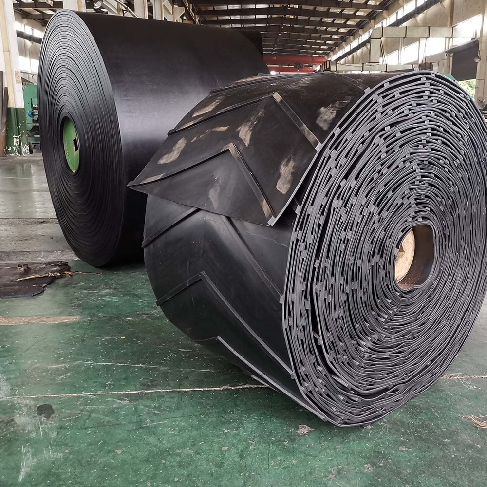
A chevron roll ready for a lift section: pattern height and pitch are matched to the duty data, not to a stock list.
The angle-to-profile matrix
| Incline on steepest section | First-choice profile | Typical profile height | Why it holds the load | Where it stops working |
|---|---|---|---|---|
| 0 to 12 degrees | Smooth cover | None | Friction alone exceeds the sliding component | Saturated fine material that behaves like a lubricant |
| 12 to 18 degrees | Smooth, or a shallow rib if the feed is wet | 0 to 5 mm | Shallow ribs catch the toe of the load when it starts to creep | Long sections where a tall rib would hit the skirt rubber |
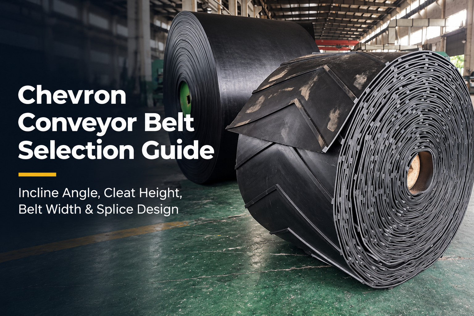
| 18 to 25 degrees | chevron conveyor belts for incline anti-slip duty, rib height sized to lump size | 6 to 10 mm | Ribs form pockets that reset the sliding surface every pitch | Free-flowing round pellets with almost no internal friction |
| 25 to 32 degrees | Deep chevron, or a sidewall conveyor belt with low cleats | Chevron 10 to 15 mm; sidewall 60 to 80 mm | Sidewalls stop lateral spread, cleats carry the load column | Very abrasive sharp rock that cuts the base of the wall |
| 32 to 40 degrees | Corrugated sidewall with cross cleats, pocket arrangement | Sidewall 80 to 120 mm | Closed pockets; the load sits on cleats rather than on friction | Belt speed above roughly 3 m/s, where pockets eject material |
| Above 40 degrees | Fully pocketed box belt, or leave the belt and use a different machine | Sidewall 120 mm and up, with cleats sized to the pocket | Load is fully enclosed by wall plus cleat | Maintenance access, return-side cleaning, and drive power all get hard |
Read the last column twice. Every profile row has a failure path, and in a port the failure path usually shows up as an unplanned stop rather than as gradual wear. If a terminal is asking a 34-degree boom to move wet iron ore fines at 4 m/s, the profile is not the only variable that has to change.
Profile height is not a free upgrade
Taller ribs carry more load, and they also do three things you may not want. They reduce the clearance under the skirt rubber at the loading point, they make the belt harder to clean on the return side, and they change how the belt tracks through the transition because the ribs make the belt stiffer in the transverse direction. On a lift section we would rather raise the rib height by 2 mm and slow the belt slightly than push a 15 mm rib through a chute that was detailed for a 6 mm one.
For sidewall assemblies there is a second dimension to settle: the wall height and the cleat pitch. A wall that is too tall for the cleat spacing lets the load column bulge between cleats and rub the wall. A wall that is too short spills over the top on the steepest part of the run. We have a longer treatment of this in our note on the sidewall conveyor belt in incline transport, and a companion piece on the corrugated sidewall conveyor belt for steep conveying that goes through the pocket geometry case by case. Both apply directly to unloader and shiploader lift segments, where the belt is short, the angle is high, and there is almost no room to add a second transfer point.
What we need before we size a profile
Six numbers get us most of the way: tonnage per hour (average and peak), loose bulk density, maximum lump size, the incline measured along the steepest section, belt speed, and whether the material is wet, sticky or free-flowing. Add the loading and discharge geometry and we can usually commit to a profile height with a margin we can explain. Take away the lump size and the incline and we are guessing, which is the point at which a specification stops being engineering. Terminals that buy through wholesale conveyor belts channels without those six numbers often end up with a rib pattern chosen by availability rather than by duty.
Materials with awkward habits
Cement clinker and sinter are abrasive and hot, so the cover compound has to survive both. Fertiliser and urea prills are free-flowing and often damp, which pushes the required incline down for a given profile. Petroleum coke is light and dusty, and the fines behave almost like a liquid on a wet belt. Grain and oilseed are handled gently, and the limiting factor becomes the cleanliness of the return strand rather than the incline. Wood chips bridge and mat, so the chute design does more work than the belt profile.None of these are exotic, and all of them have shipped through at least one terminal where the original belt specification did not reflect the material's actual behavior in the rain.
04Steep Transfer Geometry: Transition, Take-Up and Backstop
Once the profile is settled, the geometry decides whether the belt survives. A steep transfer section is short, which means the distances that absorb stress are also short. Three of them cause most of the trouble.
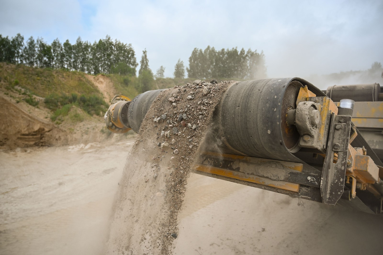
Discharge onto a yard conveyor: centering the load is worth more than any downstream tracking device.
Transition distance from the last troughing idler to the pulley
The belt has to change from a troughed shape at the idlers to a flat shape at the pulley, and it has to do it in the distance available. Too short and the edges are stretched beyond their elastic limit; too long and the load spills before the belt reaches the pulley. The transition length scales with the troughing angle and the belt's transverse stiffness, and a higher-modulus carcass needs more distance for the same trough. On a shiploader boom there is rarely space to lengthen it, so we change what we can: a slightly reduced trough angle on the final idler set, a lower take-up, and more careful pulley crowning. This is one of those cases where the belt supplier and the machine builder have to talk, and where a belt order placed purely on price tends to reveal the gap.
Take-up travel and the counterweight question
An incline belt stretches. Elastic elongation plus permanent stretch over the first months can consume a large part of the take-up stroke, and a gravity take-up that starts near the top of its travel will hit the stop long before the belt is worn out. Before quoting, we ask for the take-up type, the total available stroke, the counterweight mass, and whether the take-up is at the head or the tail. Fabric carcasses typically stretch more and settle faster than steel cord, which is why a steel cord belt can rescue a machine that was designed with a short take-up tower. It is also why we tell terminals to record the take-up position at commissioning and again after the first hundred hours. That single number predicts a surprising share of future belt problems.
Backstops, brakes and roll-back
Any incline above about 8 degrees with a loaded belt needs to be examined for reverse running. A backstop on the drive pulley stops the belt from running backwards when the motor is de-energized, and a brake does a different job by controlling how the machine comes to rest. Port machines often need both, because a boom can be pointing up while a vessel is being loaded and down while the same machine is being repositioned. What we watch is whether the drive has a holdback that engages immediately or one that allows a momentary roll-back first. A momentary roll-back on a 30-degree lift section with a full belt can put a shock load through the splice that is worse than any start.
Vertical curves and the convex radius
Where a conveyor goes from horizontal to a steep incline, the concave transition radius has to be large enough that the belt does not lift off the idlers, and the convex radius at the top has to be large enough that the belt edges do not buckle. On a fixed yard conveyor these curves are set by the structure, and the belt simply has to cope. On a boom they change as the machine luffs, which is one more reason boom belts get a low-stretch carcass and a careful tension calculation. If a terminal sends us a curve drawing with a radius we think is tight for the selected carcass, we say so before the belt is built rather than after the first edge crack appears.
05Spillage and Carryback: The Countermeasure List
Spillage at a port is not only a housekeeping cost. Material on the jetty goes into the water, and terminals with environmental conditions in their operating licence care about that. Carryback is the more insidious of the two because it attacks the belt from underneath, where nobody looks until the tracking has already gone wrong. The list below is the one we walk through with terminal maintenance teams, in roughly the order we would spend money.
Countermeasures by location
| Countermeasure | Where it goes | What it actually fixes | Detail that matters |
|---|---|---|---|
| Skirt rubber and skirt board | Loading zone, both sides | Edge spillage as the load settles | Set clearance to the belt, not to the structure; check it after the first week of running |
| Impact bed under the chute | Directly below the material stream | Top cover damage and ply separation from impact | Bars or pads, matched to lump size and drop height; keeps a straight line under the load |
| Primary cleaner, tungsten or carbide tipped | Head pulley, carrying side | Most of the carryback mass | Blade pressure has to be adjustable; too much pressure wears the cover faster than the cleaner saves |
| Secondary cleaner | After the head pulley, on the return strand | The fines the primary blade leaves behind | The combination of primary plus secondary is what makes a return strand stay clean |
| Diagonal plow or V-plow | Return strand, before the tail pulley | Material that has already passed the cleaners | Essential where the tail pulley is close to the ground or the sea |
| Chute drop control, rock box or dead box | Inside the transfer chute | Impact energy and dust generation | A short drop with a controlled stream beats a tall chute every time |
| Enclosed transfer tower and dust extraction | Chute and loading zone | Wind-blown dust and material loss in crosswind | Seal the tower, then give the air somewhere to go; a sealed box with no extraction finds its own way out |
| Belt training idlers and a self-aligning tail | Loading zone and full return run | Misalignment caused by uneven carryback | Fix the carryback first; trainers treat the symptom |
Our order of spending is the table read top to bottom, with one exception. If a lean-to sea breeze is blowing across the loading zone, we would move the dust sealing and the chute drop control up the list, because that is where a terminal loses material where the public can see it.
Carryback is a return-side problem, so inspect the return side
When we are asked to look at a belt that keeps wandering off-center, the first thing we do is walk the return strand. Fines trapped between the belt and the return idlers create a slightly different friction on each side of the belt, and the belt takes the path of least resistance. The fix is never a new tracking frame. It is a cleaner arrangement that actually removes the fines, plus training idlers that hold the belt while the cleaner is being maintained. Cleaners need maintenance. If there is no access platform and no inspection routine, the best cleaner in the terminal will stop working within a month and nobody will notice until the pile of spillage under the pulley gets too big to ignore.
Spillage on an incline behaves differently
On a lift section, spillage does not simply fall off the edge. It runs back down the belt and accumulates against anything in its path, which is usually the loading skirt or the first idler set after the loading point. That accumulated material then lifts the belt, or worse, jams against a moving edge. If a terminal reports spillage on the incline of an unloader, we look at three things before we touch the belt specification: whether the load is centered, whether the feed rate is being changed rapidly, and whether the load is arriving at a velocity that makes it bounce. A belt change will not fix a chute that is unloading off-center.
One practical field note. We have seen more than one terminal solve a persistent incline spillage problem by reducing the average feed rate slightly and raising the belt speed, which flattens the load profile on the belt. Belt speed changes are not free, since wear rises with speed, but if the alternative is a chute rebuild during a shutdown window that does not exist, it is a reasonable temporary measure. We say temporary on purpose.
06Salt Air and High Humidity: Selection Notes for Marine Sites
Coastal terminals do not just add water to the picture. They add chloride, ozone, ultraviolet exposure, wind-borne grit, and a temperature cycle that swings from a cold night on the jetty to a hot afternoon with the sun on a black belt. Belting that performs for a decade in a dry inland plant can look tired after four or five years at a quay. The specification does not need to be exotic, but it does need to be deliberate.
Carcass choice under salt exposure
For fabric carcasses, we favor polyester in the warp for wet coastal duty. Nylon has excellent fatigue resistance and impact tolerance, and it also loses strength when wet, which matters when a belt runs in a marine atmosphere for years without ever drying out completely. EP constructions give a better balance of wet strength, low stretch and price for the belt lengths a terminal actually orders. Where the tension or the take-up travel pushes us toward steel cord, the deciding question is cord corrosion. A steel cord belt that takes moisture into the cord bundle loses strength from the inside, and the damage is invisible from the outside until the splice or the cord itself fails. For marine duty we specify a compound with high rubber penetration between the cords, and we seal cord ends at every splice.
Covers, and why abrasion grade is not the whole answer
A lot of port specifications stop at an abrasion class and a cover thickness. That covers the chute and the loading point. It does not cover the ozone and ultraviolet attack that ages the cover from the outside, or the way salt-laden grit embeds in a soft compound and then cuts the surface from within as the belt flexes. A chloroprene-based cover resists weathering and ozone far better than a plain styrene-butadiene compound and holds up reasonably to abrasion, which is why it appears so often on coastal conveyors that see sun and rain. A general-purpose cover can be the right economic choice on a fully enclosed yard conveyor. On an exposed boom or quay belt, it usually is not.
What we will not do is publish an abrasion figure as if it were a measured value for every compound we offer. Our approach is simpler. We define the cover by duty, we supply the compound with the batch documentation that applies to it, and where a terminal needs third-party test evidence, we agree on the test scope before the order rather than after. Buyers who want to see how the material and mix control works can look at how we run the conveyor belt factory side of the business, which is where the answer to most cover-life arguments actually lives.
Marine selection notes at a glance
| Item | Inland default | What we specify for coastal port duty | Reason |
|---|---|---|---|
| Fabric carcass | NN or EP, whichever is cheaper | EP, with wet-strength retention considered | Nylon loses strength when wet; coastal belts stay damp |
| Steel cord | Standard rubber penetration | High penetration compound, sealed cord ends | Chloride ingress corrodes cords invisibly from inside the bundle |
| Cover compound | General purpose | Weather and ozone resistant, abrasion grade for exposed runs | UV and ozone crack a general-purpose cover long before it wears out |
| Splice | Vulcanized, cold bond acceptable on low tension | Hot vulcanized, steps or fingers to match construction | Cold bond is moisture sensitive during cure and has less margin on a lift |
| Fasteners and clamps | Zinc plated | Hot dip galvanized or stainless at skirt and chute lines | Plated parts rust through and drop material into the load path |
| Rollers and idlers | Standard bearing, standard seal | Sealed for life or regreasable with marine-duty seals | A seized return idler cuts the bottom cover within days |
Drive components face the same air
Belts get the attention, but the drives around them age just as fast. Boom luffing gearboxes, hydraulic pump drives, dust collector fans, apron feeder drives and small package units on the machine all carry power through V-belts, and a matched set that has run for years in a marine atmosphere will not behave like a new one. When a terminal sends us a drive that keeps throwing belts, we usually find mismatched sections or a sheave that has worn into a groove profile no longer suited to the belt. A transmission belt manufacturer is only useful in that conversation if it can also tell you what groove the belt needs, and there is a reason we ask for sheave dimensions alongside the belt number. Our V-belt manufacturer range is modest compared with the belting side of the plant, but it covers the wrapped and cogged sections that terminal drives actually use.
07Splice Strength in Lift Sections
The splice is the weakest link in any conveyor, and on a lift section it is also the most loaded and the most frequently cycled. Two things drive that. First, the tension is higher because the belt is lifting material rather than just moving it. Second, the number of load cycles is higher because a port machine starts and stops so often. A splice that is perfectly adequate on a 200 m yard conveyor may be the first thing to fail on a 28-degree boom.
Splice types and where they belong
| Splice method | Best fit | What we specify | Weakness on a lift section |
|---|---|---|---|
| Hot vulcanized stepped splice | Fabric carcass, all port duties including lift sections | Steps matched to ply count, controlled cure pressure and time, joint staggered to the belt centerline | Workmanship; a splice closed at the wrong temperature is a long-term failure with no visible symptom |
| Hot vulcanized finger or overlap splice | Steel cord carcass | Cord-by-cord layout, correct step length for the cord pitch, sealed cut ends | Cord pull-out and corrosion at the cut ends, especially in a marine atmosphere |
| Cold bonded splice | Emergency repair, low tension, available shutdown window | Surface preparation, cure time at the actual site temperature and humidity | Cure is humidity sensitive; coastal sites are the worst place to gamble on it |
| Mechanical fastener | Short temporary runs, low tension, no vulcanizing access | Plate arrangement matched to belt thickness, corrosion-resistant hardware | Fasteners pull through under repeated starts and corrode in salt air |
Published splice efficiency figures for fabric belts commonly sit somewhere in the 60 to 90 percent band relative to belt strength, depending on construction, step count and workmanship, and steel cord splices are usually quoted lower as a dynamic value than a fabric splice.We treat those as industry ranges rather than as a number to design to, because the only figure that matters is the one your belt and your splice actually deliver. What we do instead is make sure the belt rating, the number of steps and the cure procedure are agreed before the belt leaves Ningbo.
Starts, stops and the peak the splice actually sees
Steady state is not the problem. A direct-on-line start on a loaded incline can put a transient tension through the belt that is well above the running value, and a machine started twenty-five times a day accumulates those peaks quickly. When a terminal tells us it is replacing splices every few months, the first questions are about the drive, not the belt. Is there a soft starter or a variable-frequency drive, and is the ramp actually being used? How many starts per hour? Is the belt being started with the boom loaded, or is the machine being emptied first? Does the take-up allow the belt to relax between starts? A controlled ramp, a take-up with usable stroke, and a habit of not restarting a fully loaded steep belt will do more for splice life than any change of rubber compound.
Cure quality is a site issue
Vulcanizing on a jetty in a marine atmosphere is not the same as vulcanizing inside a plant. Wind pulls heat out of the press, humidity affects the bonding surfaces, and the crew may be working on a boom where the belt cannot be brought down to level ground. We would rather see a splice cured at a somewhat conservative temperature for longer, with the joint protected from wind, than a fast cure that looks good on the outside. If a port has a record of splices that open within a year, we ask to see the cure data and the joint preparation photos. That is not a formality. The photos tell you more about the next splice than the compound data sheet does.
08A Worked Capability and Incline Check
Numbers settle arguments. Below is a calculation we run in much the same order for a terminal that gives us a capacity, a route and a bulk density. It is an illustration with round numbers, not a quotation, and every real job gets re-run against the actual layout, the applicable design standard and the drive arrangement.
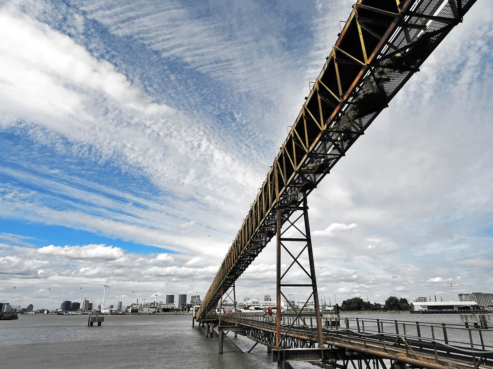
A quay-side transfer where incline, lump size and belt speed all have to be settled together.
Step 1: write down the duty data
| Parameter | Value used | Source |
|---|---|---|
| Material | Imported steam coal, 150 mm top size | Terminal |
| Loose bulk density | 0.85 t/m3 | Terminal, confirmed at the pile |
| Nominal and peak capacity | 900 t/h nominal, 1,000 t/h peak | Terminal |
| Route | 140 m centres, 22 m lift | General arrangement drawing |
| Resulting incline | About 9 degrees average, 13 degrees on the steepest panel | arctan of lift over centres, then read off the profile |
| Belt speed | 3.15 m/s | Chosen to limit degradation and dust at 150 mm top size |
Step 2: required load cross-section
The basic relationship is simple. Tonnage equals belt speed times the load cross-section times bulk density, with the units reconciled:
Q = 3,600 x A x v x rho
where Q is tonnes per hour, A is the load cross-section in square meters, v is belt speed in meters per second, and rho is loose bulk density in tonnes per cubic meter. The 3,600 converts seconds to hours. Rearranged, and with an incline capacity factor applied, we get:
A required = Q / (3,600 x v x rho x k)
For a coal load on a three-roll 35-degree troughing set, an average surcharge angle of about 25 degrees and a 1,000 mm belt width, the available cross-section is roughly 0.111 m2. That number depends on troughing angle, belt width, idler configuration and the operating surcharge angle, so it changes from job to job.
Take the steepest panel at 13 degrees and use an incline capacity factor of 0.96, which is representative of the published correction tables for a material like coal at this angle:
A required = 900 / (3,600 x 3.15 x 0.85 x 0.96) = 900 / 9,639 = 0.0934 m2
Available area is 0.111 m2, a margin of about 19 percent over the requirement. Now check what the conveyor actually delivers with the belt we selected:
Q = 3,600 x 0.111 x 3.15 x 0.85 x 0.96 = 1,027 t/h
Against a 1,000 t/h peak, that is a margin of under 3 percent. Fine on paper, uncomfortable in practice, because loose bulk density moves with moisture and a wet coal can be noticeably denser than the number the terminal gave us. This is exactly the point where we would quote a 1,200 mm option alongside the 1,000 mm one and let the terminal decide whether it wants surge margin or capital savings.
Step 3: check the incline against the material
A smooth belt can only hold material while the friction between the load and the cover exceeds the sliding component of gravity. In practice the working rule is that a smooth belt is safe up to something like the material's surcharge angle minus a margin of three to five degrees. Coal at a 25-degree surcharge angle gives a usable smooth-belt incline in the high teens. At 13 degrees, a smooth belt is comfortable, and a chevron profile would be a needless complication on this conveyor.
Now put the same tonnage on a shiploader lift segment at 28 degrees and the picture changes. Applying an incline capacity factor of 0.85 for a plain belt at that angle, the required cross-section becomes:
A required = 900 / (3,600 x 3.15 x 0.85 x 0.85) = 900 / 8,193 = 0.1099 m2
That leaves barely one percent margin on a 1,000 mm belt, which is not a specification, it is a hope. Two answers are available. Go to a 1,200 mm belt and accept a wider machine, or keep the width and move to a pocketed belt, where the cleats and walls carry the load and the capacity penalty is closer to 0.95 than 0.85. Redoing the arithmetic with the lower penalty:
A required = 900 / (3,600 x 3.15 x 0.85 x 0.95) = 900 / 9,157 = 0.0983 m2
That is a margin of about 13 percent on the original width. This is the argument we make to terminals that treat the profile as a grip detail. On a steep section the profile is a capacity decision, and the difference between a 1 percent margin and a 13 percent margin is the difference between a machine that runs at the design rate and one that the operator quietly de-rates.
Step 4: tension, power and the belt rating
Material load per meter of belt is Q divided by 3.6 v, which gives 900 / 11.34 = 79 kg/m. Add a belt mass of roughly 17 kg/m for a 1,000 mm EP construction and 22 kg/m for the rotating idler mass. With an artificial friction coefficient of 0.025, the main resistance over 140 m comes out near 4.1 kN. The lift term is the one that dominates: mass per meter times gravity times lift height, 79.4 x 9.81 x 22, which is about 17.1 kN. Add secondary resistances at roughly 15 percent and the total effective tension lands near 24.4 kN.
Power follows from tension times speed. At 3.15 m/s that is 76.8 kW at the belt, and about 85 kW at the motor shaft once a drive efficiency of 0.9 is allowed for, so a 90 kW motor is the natural selection. Now the tensions. With a lagged head pulley, a friction coefficient of 0.35 and 180 degrees of wrap, the ratio of tight side to slack side is about 3.0. For an effective tension of 24.4 kN, the slack side tension works out at 12.2 kN and the tight side at 36.6 kN.
Then check sag. To keep sag under one percent on a 1.2 m idler spacing, the slack side tension must be at least 14.2 kN, which is above the 12.2 kN the drive ratio produces. The take-up has to supply the difference. Raise the slack side to 15 kN and the tight side becomes 39.4 kN. That is the number the belt has to survive, and it is why we ask for counterweight or take-up data before quoting rather than after. An EP500 belt at 1,000 mm has a rated strength of 500 kN; with a working safety factor of ten, the allowable working tension is 50 kN. At 39.4 kN we would be using about 79 percent of that allowance on a machine that starts and stops constantly. Move to EP630 and utilization drops to roughly 63 percent. For a port lift section with twenty-plus starts a day, that is the selection we would put forward.
Step 5: read the answer back into the specification
The arithmetic produced four decisions. A 1,000 mm EP belt with a wear-resistant smooth cover for the yard-to-quay run, with a 1,200 mm option quoted for surge margin. A pocketed or deeply ribbed belt at the same width for the 28-degree lift segment, because the profile pays for itself in retained capacity. A carcass upgraded from EP500 to EP630 to keep working tension in a sensible band. And a take-up requirement that has to be confirmed against the actual counterweight before the order is released. None of that came from a catalogue. All of it came from six numbers and twenty minutes with a calculator.
09Reading the Terminal Layout Before You Quote a Belt
Half of what determines whether a port conveyor belt project goes smoothly is not in the belt specification at all. It is in the layout, the access and the shutdown plan. We ask about these before we commit a delivery date, because a belt that cannot be installed is not a belt.
Roll size, coil weight and how the belt gets in
Conveyor belts arrive on rolls, and on a port project the roll is often the problem. A long yard conveyor might want a single 400 m length to cut the number of splices, but that roll can weigh several tonnes and may not fit through the access door of the transfer tower, up the boom stair, or under the crane that is available on the jetty. We would rather design two splices than discover on installation day that the roll has to be cut anyway. Tell us the crane capacity, the access opening, and the largest roll diameter the machine can accept, and we will match the coil lengths to it. This is also the point where a terminal should decide how many spare rolls it wants to keep, because a damaged belt on a shiploader is not something you want to source on a two-day turnaround during peak season.
Shutdown windows, not delivery dates
A port belt change happens inside a shutdown window, and the window is usually measured in hours. Belt delivery is therefore only half the schedule. The other half is splice time, which depends on the number of splices, the method, the number of crews, and whether the press can be positioned at each joint. On a lift section with a boom, splicing can require moving the machine to a service angle and blocking it. We have seen a project where the belt arrived on time and the installation still took four days because nobody had allowed for press handling on the boom. Ask your belt supplier for the splice time estimate per joint in writing, and then add contingency. Anyone who gives you a single number without asking about access is guessing.
Order quantities, lead time and payment terms
Port projects come in two shapes. There is the new build, where the belt is one line item inside a large package and the schedule is driven by the machine builder. And there is the replacement, where a terminal needs a belt in a specific width, length and construction and needs it fast. For the second case, the practical facts are these. Our standard minimum order for conveyor belting is around 50 m per type, normal lead time is about 30 days, and we run an expedited channel that can land a belt in roughly 15 to 20 days when the construction is one we already produce. Samples for a new compound or profile take two to five days so a terminal can check the surface, the ply structure and the edge cut before committing to a full roll. Payment is normally T/T with 30 percent on order and the balance before shipment, or L/C where the contract calls for it. None of that is remarkable, and it is worth knowing before you build a schedule around an optimistic assumption.
10Specification, Verification and What We Ask Before Quoting
A good belt order starts with a clear data set. The list below is the one we send to terminal engineers and EPC package managers, and it is also a reasonable template to use when you approach any supplier. If a supplier can price the job without asking for most of it, ask yourself what they are assuming.
The pre-quote data set
Material and duty: material name, loose bulk density, maximum lump size, moisture range, temperature range, abrasiveness and any chemical content. Throughput: nominal tonnage, peak tonnage, hours per day, and how the feed varies. Geometry: centres, lift or incline on the steepest section, troughing angle, idler spacing, pulley diameters, transition distances, vertical curve radii, and take-up type with available stroke. Drive: motor power and speed, starting method, starts per hour, backstop or brake arrangement. Environment: indoor or exposed, coastal or inland, ambient temperature range, wind exposure. Installation: access, crane capacity, maximum roll weight and diameter, shutdown window, and who will perform the splicing.
Once we have that, we can respond with a construction rather than a guess: carcass type and ply count, cover grades and thicknesses, tension rating, profile or sidewall geometry, splice method, coil lengths and roll weights, and a splice time estimate. Where a terminal works through a products catalogue or a local stockist, the same data set is what allows the stockist to pick the right item off the shelf instead of the nearest one.
What we will not put in a quote
We do not publish abrasion or adhesion numbers for a compound unless they come from a test we have run on that compound, and we do not offer a service life guarantee expressed in years, because the number would be meaningless without the terminal's own operating data. What we will do is tie the offer to a defined construction and to the batch documentation that belongs to it, including the routine checks we run on incoming rubber and fabric, on the calendering and building process, on finished dimensions, and on the laboratory samples taken from the batch. If a terminal or its engineer wants a specific third-party test carried out on the delivered belt, we agree the scope and the sampling plan up front. That is a more useful commitment than a large number on a brochure.
11Where Port Belt Projects Go Wrong
Five patterns account for most of the disputes we see on terminal work. They are all avoidable, and none of them are about rubber quality.
The five recurring mistakes
One: specifying the lift section and the yard section identically. The two conveyors have different jobs. A single belt construction across both usually means the lift section is under-profiled and the yard section is over-priced.
Two: buying the profile from a picture. Chevron and sidewall geometry look interchangeable in a photograph and are not. Rib height, pitch, wall height and cleat spacing each have an effect on capacity, cleaning and skirt clearance.
Three: leaving the transfer chute out of the conversation. The best belt in the terminal cannot compensate for a chute that dumps the load onto one edge. If the spillage pattern is asymmetric, the chute is the first suspect, not the belt.
Four: ignoring the take-up. We have seen perfectly good belts blamed for tracking and slip problems that came down to a take-up with no usable stroke. Measure the position, write it down, and compare it six months later.
Five: treating the splice as installation labour rather than engineering. The splice is the highest-risk part of the belt and it is made on site, in weather, on a schedule. Give it a procedure, a supervisor and a cure record.

12Frequently Asked Questions
Can a port conveyor belt run steeper than 30 degrees?
Yes, and most ship unloader and shiploader lift segments do. Above roughly 30 degrees you are no longer relying on friction between the load and the cover, so a smooth belt is the wrong tool. A deep chevron pattern carries you into the low thirties. Past that, a corrugated sidewall belt with cross cleats forms pockets that hold the load mechanically, and beyond about 40 degrees a fully pocketed box belt is the usual answer. The limit is rarely gravity alone. It is belt speed, belt cleaning, splice life and maintenance access, all of which get harder as the angle rises. We would want the incline measured along the steepest section, not taken from the average of the whole boom, before recommending a profile.
Chevron or sidewall: how do we choose?
Use chevron where the belt runs on conventional troughing idlers and the incline is moderate, roughly 18 to 32 degrees, and the material is not extremely free-flowing. Use a sidewall conveyor belt where the incline is steeper, where you need cross cleats to carry the load column, or where lateral spillage is a problem in itself. On a lift section inside a machine, the deciding factor is often space. A pocketed belt does more work in the same width, which matters when the boom is already built and a wider belt is not an option. Both approaches are covered in more detail in the practical guides in our blog index.
What cover thickness should a coastal terminal specify?
As a working range, 6 to 8 mm of top cover is common on yard and quay conveyors handling coal or ore, with 3 to 5 mm on the bottom cover where the return strand is cleaned properly. Loading zones with a high drop want more, because cover is what you sacrifice to impact. Two details matter more than the number. The compound has to resist weathering and ozone if the belt is exposed, and the bottom cover has to have enough thickness to survive a return idler that seizes before anyone notices. If a terminal runs heavy fines and infrequent cleaning, thin bottom covers are a false economy.
Do we need steel cord belting for a ship unloader?
Not automatically. Steel cord earns its place where tension is very high, where the take-up stroke is short and low stretch matters, or where the machine is long and heavily loaded. On a short, steep lift inside a shiploader or unloader, a high ply fabric carcass often does the job with less complication and an easier splice. If the belt does need steel cord, the port environment adds one condition: specify a compound with high rubber penetration between the cords and make sure the splice crew seals every cut cord end. An unsealed cord end in salt air is a corrosion site that spreads inside the bundle where you cannot see it.
What causes spillage at a transfer point when the skirt rubber is new?
Usually one of four things. The chute is not centered on the belt, so the load lands off-axis and one skirt has to contain material the other never sees. The drop height is too great and the material arrives with enough energy to bounce past the skirt. The skirt clearance was set to the structure rather than to the belt, leaving a gap that fines can squeeze through. Or the feed rate is being changed quickly enough that the load surges past the loading zone before it can settle. Adding skirt pressure is rarely the fix; it just wears the edges faster.
How long should a port conveyor belt last?
Any number we gave you without seeing the terminal would be worthless. Service life is driven by the cover grade, the material's abrasiveness, the cleanliness of the return strand, the alignment, the number of starts, and how often the belt is allowed to run with a damaged edge. What we can do is make the wear measurable. Record the cover thickness at a set of marked points at commissioning, re-measure after six months, and you will have a wear rate for your own terminal rather than a figure from someone else's brochure. That rate is what should drive your next specification.
Can a port belt be spliced on the quay?
It is routinely done, but the conditions deserve attention.Wind pulls heat out of the press, humidity affects bonding surfaces, and the belt may be sitting at an angle that makes it hard to align the plies or cords. We prefer a longer cure at a controlled temperature with the joint shielded from wind over a short cure that reports well on paper.If a terminal has a history of splices opening within a year, the cure record and the joint preparation photos are worth more than any change of compound.
What should be on the RFQ for a port conveyor belt?
Material and bulk density, maximum lump size, moisture and temperature range, nominal and peak tonnage, centres and lift, incline on the steepest section, troughing angle, pulley diameters, take-up type and stroke, motor power and starting method, starts per hour, indoor or coastal exposure, roll weight and diameter limits, and who splices the belt. Add the number of spares you want to hold and your target installation window. With that in hand, a competent supplier can respond with a construction, a splice plan and a realistic date instead of a price and a hope.
If you are working through a port expansion, a machine replacement or a belt that keeps failing, send us the layout and the duty data. We will tell you what we would specify and, just as usefully, what we would not. Reach us at sales@sinoconve.com or through the contact page on sinoconve.com.
Related Products You May Need
| Product | Where it fits on a port conveyor |
|---|---|
| Rubber Conveyor Belt | Yard-to-quay runs, transfer towers and yard conveyors where a flat, wear-resistant belt is the right answer. |
| EP Rubber Conveyor Belt | Low-stretch fabric carcass for inclined runs, wet coastal duty and machines with limited take-up stroke. |
| Steel Cord Conveyor Belt | High-tension lift sections and long hauls where elastic stretch has to stay small. |
| Chevron and Sidewall Conveyor Belts | Unloader and shiploader lift segments, stacking and reclaiming at angles a smooth belt cannot hold. |
| Conveyor Rollers and Idlers | Impact, troughing and return idlers with sealing suited to a salt-laden marine atmosphere. |
| Full Product Catalog | Belting, drive belts and components for terminal projects, with custom widths, thicknesses and cover grades. |
Related Blog Posts
- Sidewall Conveyor Belts in Incline Transport - wall height, cleat pitch and how pocket geometry holds a load on a steep run.
- Chevron Conveyor Belts for Incline Anti-Slip Duty - rib height and pitch selection for moderate inclines and wet material.
- Chevron Conveyor Belts in Steep Bulk Handling - profile design for high-angle transfer and discharge sections.
- Corrugated Sidewall Conveyor Belt for Steep Conveying - case-by-case pocket geometry for angles above 30 degrees.
- Industrial Conveyor Belt Supplier Checklist for Mining, Cement and Port - what to verify before a bulk belt order is released.
- Conveyor Belt Storage, Handling and Installation Checklist - roll handling, installation and the splice steps that decide belt life.